
Reinforced Bag

a technology of reinforced bags and bags, applied in the field of bags, can solve the problems of bags being subjected to one or more types of potentially failure-causing strain, and achieve the effect of improving the value of bags

Inactive Publication Date: 2011-03-03
MONDI BAGS USA
View PDF69 Cites 45 Cited by
  • Summary
  • Abstract
  • Description
  • Claims
  • Application Information

AI Technical Summary

Benefits of technology

[0006]In accordance with one aspect of this disclosure, a bag has a reinforcement that is configured in a predetermined manner for reinforcing at least a portion of the bag. For example, one or more predetermined areas of the bag may be reinforced while one or more other predetermined areas of the bag are not reinforced. The bag may have one or more layers (e.g., ply(s)), and may be reinforced by placing and affixing reinforcing media in selected areas. The reinforcing seeks to improve the value of the bag. The nature of the reinforcing media—its dimensions and structural properties—may be selected with respect to targeted uses of the bag. Regarding the targeted uses of the bag, the bag may be subjected to one or more types of potentially failure-causing strain (e.g. bending, twisting, puncture, tensile, compression etc.) during the useful life of the bag. For example, the bag may be stressed during filling the bag with product, top sealing, conveying by hand or machine, loading and stacking on a pallet (or other carrying devices), transportation, storage, selling and final use by the consumer.
[0009]In accordance with one aspect of this disclosure, a composite bag (e.g., a multiwall bag and / or a reinforced bag) has opposite ends that are spaced apart from one another in a longitudinal direction, a plurality of walls that extend around the interior space of the composite bag, and a reinforcement (e.g., a reinforcing insert, sheet, ply and / or erected structure) that is reinforcing at least a portion of a wall of the plurality of walls, wherein the reinforcement may not completely circumscribe the interior space of the composite bag. In a more specific example, the reinforcement may not completely circumscribe the longitudinal axis of interior space of the composite bag. A gap may be defined between the opposite ends of the reinforcement. The gap may aid in insertion of the reinforcement, if the reinforcement is of a type that is inserted into a bag.

Problems solved by technology

Regarding the targeted uses of the bag, the bag may be subjected to one or more types of potentially failure-causing strain (e.g. bending, twisting, puncture, tensile, compression etc.) during the useful life of the bag.

Method used


Image

  • Reinforced Bag
  • Reinforced Bag
  • Reinforced Bag

Examples


first embodiment

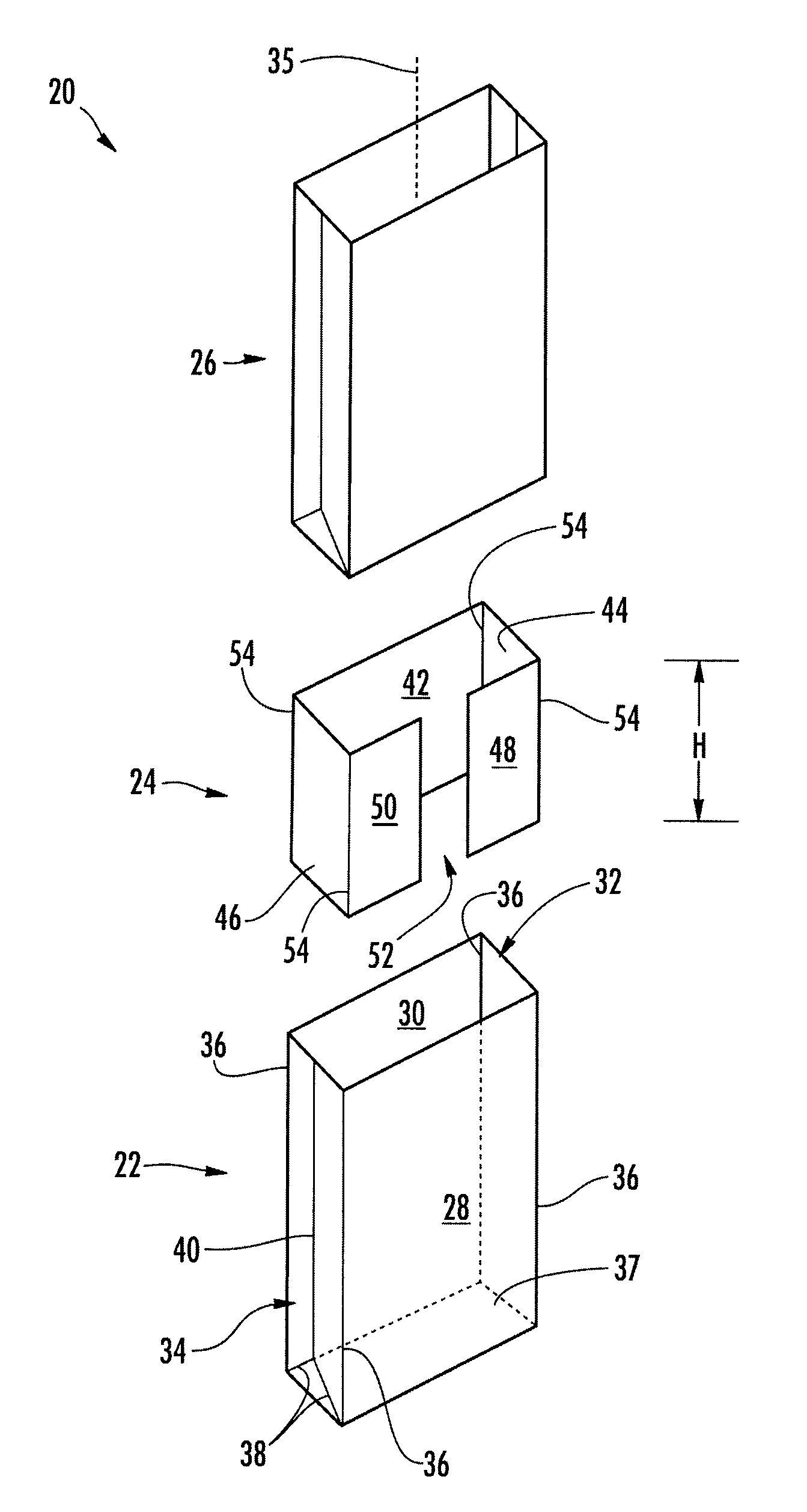
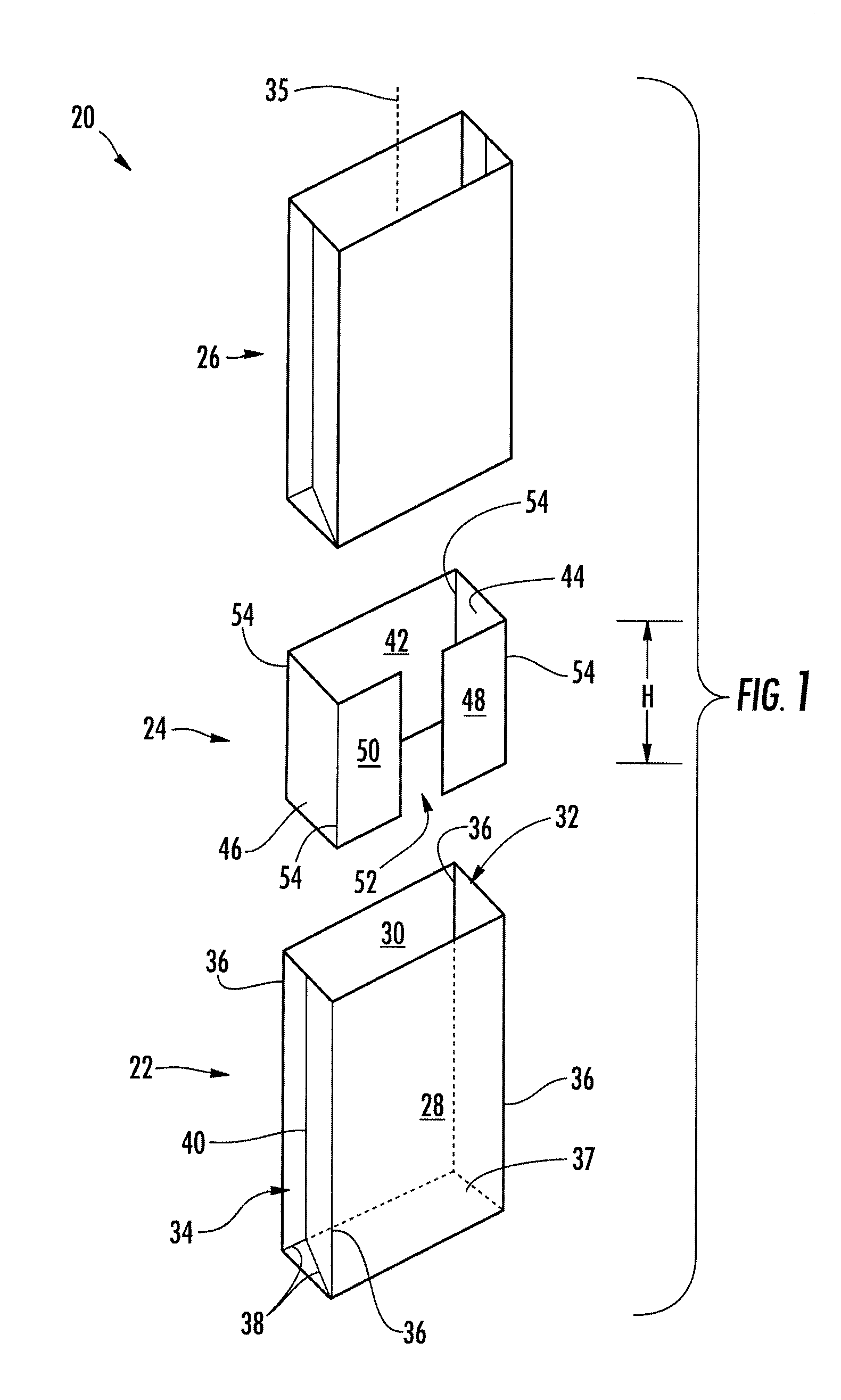
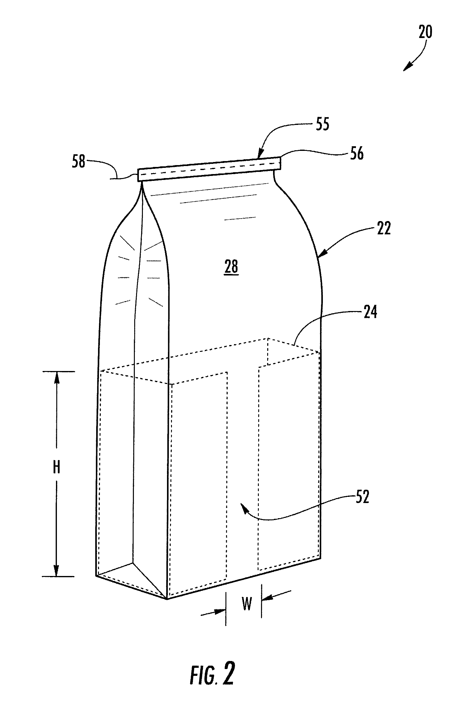
[0036]The reinforcement 24 is typically a layer (e.g., a single layer, multi-layer (e.g., multi-ply) sheet or a multilayer laminate) of material that is typically stiffer than the material from which the outer and inner bags 22, 26 are constructed. The reinforcement 24 is typically adapted and / or constructed of a material so that the reinforcement can be folded and / or bent to fit inside the outer bag 22 and reinforce the front, rear and side walls 28, 30, 32, 34 of the outer bag. The reinforcement 24 includes a rear wall 42, right and left side walls 44, 46 extending forwardly from opposite ends of the rear wall 42, and right and left front walls 48, 50 that extend toward one another from forward ends of the right and left side walls 44, 46, respectively. In accordance with the first embodiment, the free ends of the right and left front walls 48, 50 are adjacent to and spaced apart from one another so that a gap 52 is defined therebetween when the reinforcement 24 is in its final, f...

second embodiment

[0065]In accordance with the second embodiment, a multi-ply sheet 100 (e.g., a multi-layer sheet) schematically shown in FIGS. 3 and 4 may be used in the construction of a composite bag 120 (e.g., a multiwall bag) schematically shown in FIG. 5. Alternatively, the composite bag 120 may be constructed by a method of assembly in which an outer bag, reinforcement and optionally also an inner bag are respectively nested into one another. Throughout this disclosure, a ply may be more generally characterized as being a layer, and a layer may be characterized as being a ply.

[0066]FIG. 3 may be schematic because it is not illustrative of the fact that, for example and as alluded to above, one or more of the plies of the multi-ply sheet 100 may be laterally offset with respect to one another. As mentioned above, the plies may be laterally offset with regard to one another so that, when the tubular structure is formed from the multi-ply sheet 100, the longitudinal seams between the longitudina...

fourth embodiment

[0083]In accordance with the fourth embodiment and as best understood with reference to FIG. 10, substantially only the front wall 328, the closed bottom end of the bag 320, and optionally also the lower marginal portion of the rear wall 330 (FIG. 8) are intimately associated with and reinforced by the reinforcement ply 324 (e.g., a single sheet of paperboard, or any other suitable material(s)). More specifically, substantially all of each of the front wall 328 and the closed bottom end of the bag 320 are superposed with the reinforcement ply 324 (e.g., reinforcing media), and substantially all of the lower marginal portion of the rear wall 330 may also be superposed with the reinforcement ply 324.

[0084]FIG. 10 is schematic, for example, because the periphery of the reinforcement ply 324 is schematically illustrated by dashed lines since it is hidden from view within the bag 320. FIG. 9 is schematic because, for example, hidden portions of the right and left edges of the reinforceme...


PUM


Abstract

A bag has a reinforcement that is configured in a predetermined manner for reinforcing at least a portion of the bag. One or more predetermined areas of the bag may be reinforced. The bag may have one or more layers, and may be reinforced by placing and affixing reinforcing media in selected areas. The nature of the reinforcing media—its dimensions and structural properties—may be selected with respect to targeted uses of the bag. The bag may be subjected to one or more types of potentially failure-causing strain (e.g. bending, twisting, puncture, tensile, compression) during the useful life of the bag. For example, the bag may be stressed during filling the bag with product, top sealing, conveying by hand or machine, loading and stacking, transportation, storage, selling and final use by the consumer.

Description

CROSS-REFERENCE TO RELATED APPLICATIONS[0001]The present application claims the benefit of U.S. Provisional Application Nos. 61 / 237,446 and 61 / 396,115 filed Aug. 27, 2009, and May 21, 2010, respectively.TECHNICAL FIELD[0002]The present disclosure generally relates to bags and, more particularly, to composite or reinforced bags.BACKGROUND[0003]Bags, such paper bags or bags constructed of other flexible media, are widely used in numerous applications. Because of the rigors and strains to which bags are exposed in use, there has been a need to reinforce bags to prevent failure and loss of the contents of the bags. Whereas reinforced bags are known, there is always a desire for improvements.BRIEF SUMMARY OF SOME ASPECTS OF THIS DISCLOSURE[0004]According to one aspect of this disclosure, prior to making a bag, the intended use of the bag may be analyzed to identify a first area of the bag that may be exposed to higher stress than a second area of the bag. The bag may be made from a sheet...

Claims


Application Information

Patent Timeline
IPC IPC(8): B65D33/02B31B19/60
CPCB65D31/02B65D31/04B65D31/10B31B39/00B65D33/26B31B37/00B65D33/02B31B70/00B31B2155/00B31B2160/20B31B70/008B31B2170/20
Inventor HOLMES, GABRIELE R.WILHOIT, DARREL L.FILES, JOHN C.
Owner MONDI BAGS USA
Learn More