
Magnetic resonance apparatus and method

a magnetic resonance and apparatus technology, applied in the field of magnetic resonance imaging, can solve the problems of affecting image quality, affecting the use of holder materials, and affecting the signal-to-noise ratio (“snr”), so as to reduce or eliminate the production of artifacts, improve the filling factor, and improve the signal-to-noise ratio.

Active Publication Date: 2011-03-03
GREEN IMAGING TECH +1
View PDF16 Cites 82 Cited by
  • Summary
  • Abstract
  • Description
  • Claims
  • Application Information

AI Technical Summary

Benefits of technology

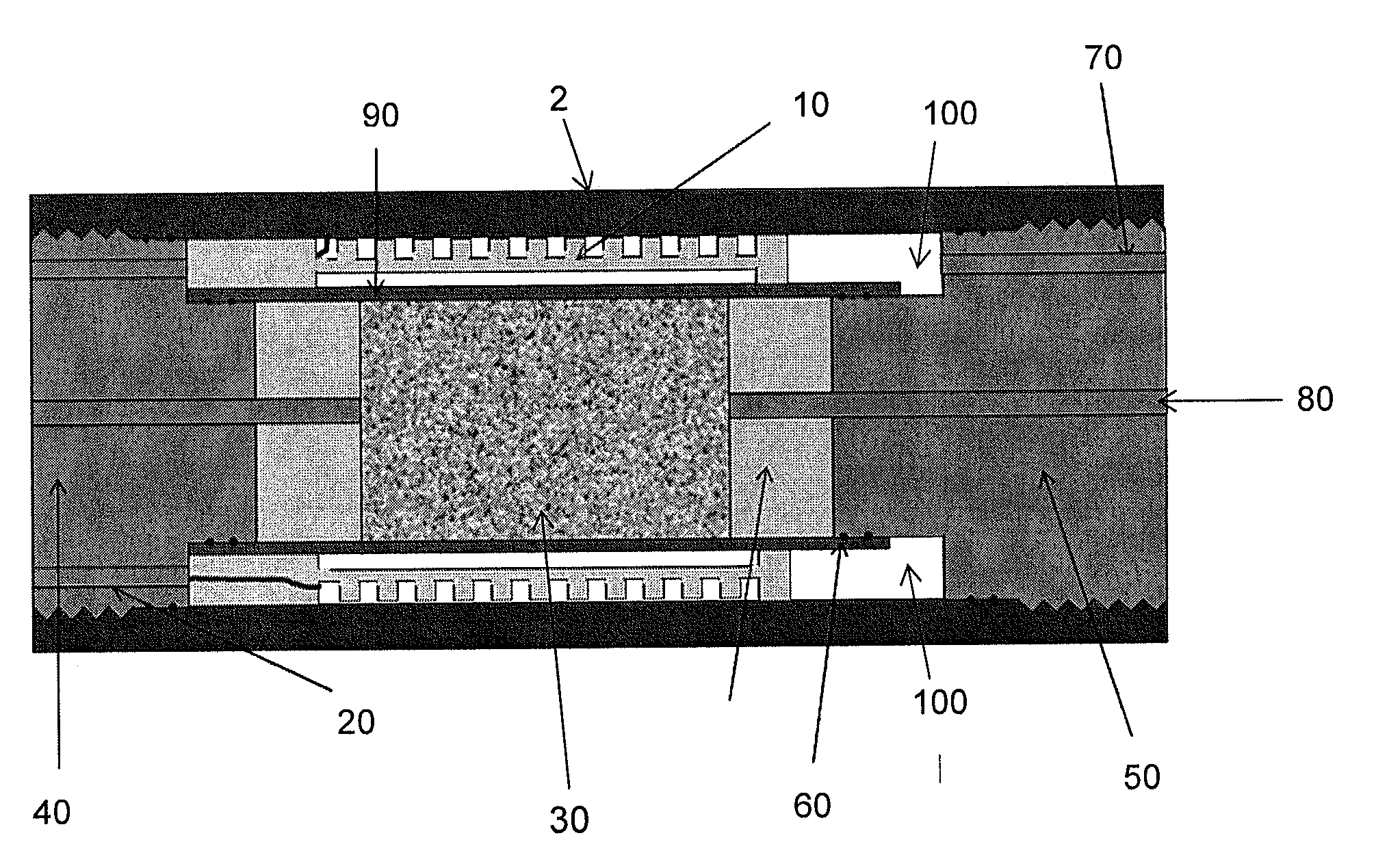
[0010]A solution to building a pressure cell for use with NMR is to move the NMR probe from outside the cell to the inside of the cell. By doing this, the design can use metal (non-magnetic) which becomes part of the electrical circuit of the NMR probe. In addition, the filling factor is greatly improved which dramatically improves the signal-to-noise ratio (“SNR”). The magnetic field gradient will be distorted due to the metal between the gradient coil and the sample but a properly designed MRI pulse sequence can greatly reduce or eliminate the artifacts produced by these distortions. Alternatively, these problems can be overcome with standard SPRITE MRI methods in combination with magnetic field gradient waveform measurements and subsequent waveform correction. Appropriate gradient waveform correction would permit the full array of gradient related MR methods to be employed (SE-SPI, conventional MRI, centric scan SPRITE, diffusion measurements).
[0016]According to another aspect, the invention relates to the use of standard SPRITE images directly without fixing deleterious waveforms where standard SPRITE is used where k space is sampled side to side.

Problems solved by technology

This presents challenges as to the materials that can be used for the holder.
Metal core holders, however, block the nuclear magnetic resonance (NMR) signal in the core sample from being detected in the RF probe.
The residual eddy currents may however still cause image-quality problems including ghosting in EPI, RARE and GRASE imaging pulse sequences, slice-profile modulation with spatial-spectral RF pulses, geometric distortion in diffusion-weighted EPI, and quantitative velocity errors in phase-contrast imaging.
Eddy currents present a particular problem in sample spaces surrounded by or in the vicinity of metals structures.
However, the gradient waveform duration is limited by the sample T2*.
In addition, implementation of this technique is relatively complex as it requires careful probe fabrication, an array of at least 3 probes, accurate probe positioning and alignment and a multi-channel receiver.
Such core holders eliminate the problems associated with using metal but are limited by the pressures and temperatures that they can sustain.

Method used


Image

  • Magnetic resonance apparatus and method
  • Magnetic resonance apparatus and method
  • Magnetic resonance apparatus and method

Examples


Embodiment Construction

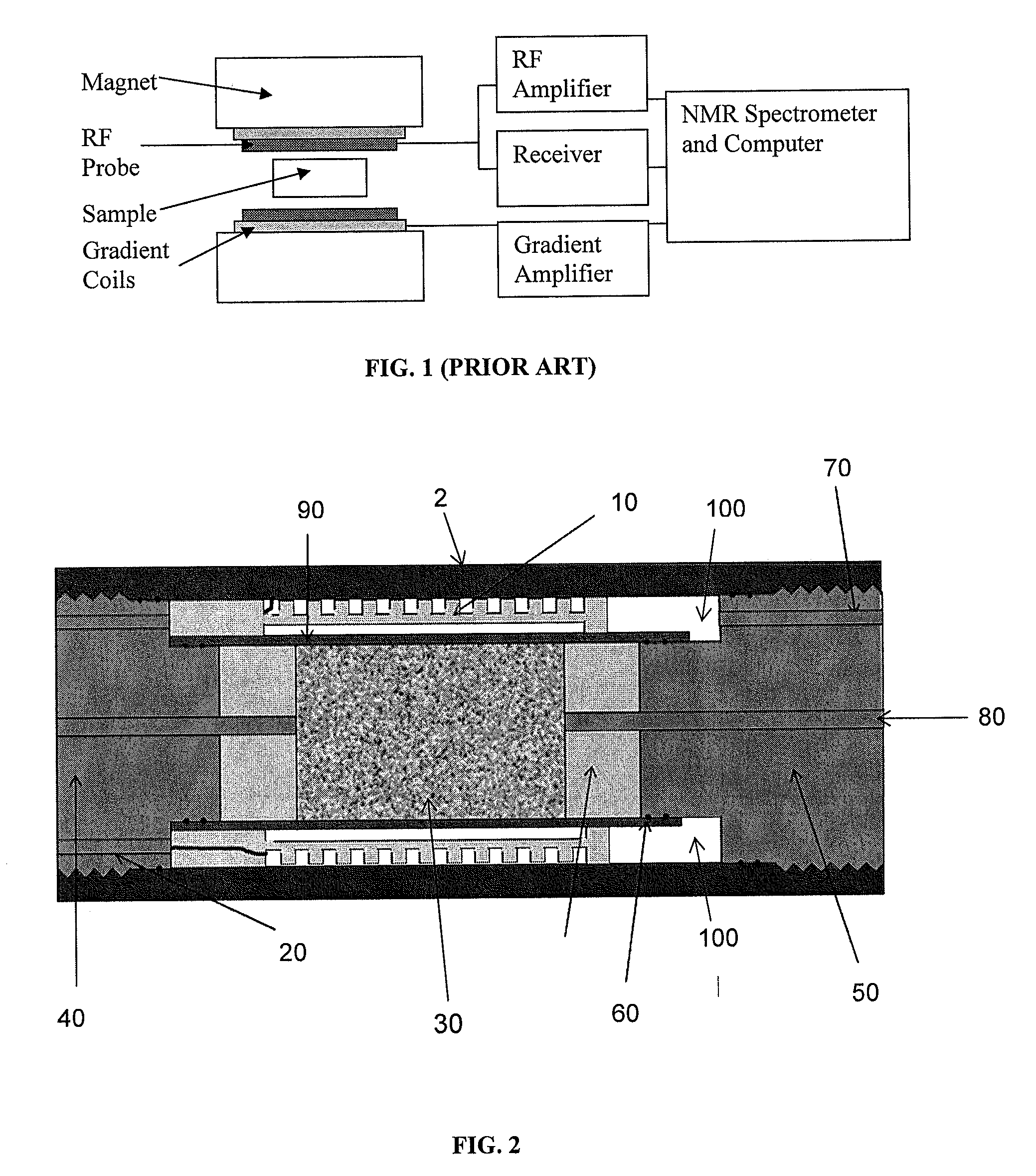
[0028]The main hardware components of a typical known MRI apparatus are shown in FIG. 1. The magnet produces the required large homogeneous static magnetic field. The RF probe and RF amplifier produces the required high power RF energy needed to excite the sample. The RF probe and receiver detects the very low level NMR signals following the RF excitation. The probe is a simple resonator that transmits and receives signals at the frequency of the NMR signal (called resonance frequency). The RF probe's sensitivity to the low level NMR signal is directly proportional to the relative volume of the probe to the sample volume. This ratio is called the filling factor. Ideally, one would want this factor to be as close to unity as possible.

[0029]The gradient coil and amplifier modifies the static magnetic field in such a way that positional information can be encoded into the detected signal and an image can be created. Typically, the magnetic field is changed linearly in the three spatial...


PUM


Abstract

An apparatus and method for performing nuclear magnetic resonance (NMR) or magnetic resonance imaging (MRI) on samples in metallic holders and vessels or in proximity to metallic objects is disclosed.

Description

CROSS REFERENCE TO RELATED APPLICATIONS[0001]This application claims benefit and priority from U.S. Provisional Patent Application Ser. No. 61 / 238,554 filed Aug. 31, 2009.FIELD[0002]The present invention relates to magnetic resonance imaging (“MRI”) apparatus and methods.BACKGROUND[0003]MRI apparatus use strong magnetic fields, high power radio frequency (“RF”) energy, and rapid precise magnetic field variations to analyse properties of materials. MRI apparatus are commonly used in clinical applications to image body tissue.[0004]MRI has also been used in other fields, notably oil and gas exploration where reservoir rock core samples are analysed to obtain information about the nature of the reservoir being investigated. In the ground, the reservoir rock can be under tremendous pressure and elevated temperatures. It is desirable to reproduce such reservoir conditions when performing tests on reservoir rock core samples. In order to do so, however, the core holder which houses the co...

Claims


Application Information

Patent Timeline
IPC IPC(8): G01R33/48G01R33/44
CPCG01R33/243G01R33/56518G01R33/4816G01R33/305
Inventor BALCOM, BRUCEGREEN, DERRICKHAN, HUI
Owner GREEN IMAGING TECH
Learn More