Eureka AIR delivers breakthrough ideas for toughest innovation challenges, trusted by R&D personnel around the world.

Undercounter ice dispenser

a dispenser and ice technology, applied in the field of undercounter ice dispensers, can solve the problems of one piece long augers, more susceptible to being damaged or bent, and more difficult to install,

Inactive Publication Date: 2011-03-03
MARMON FOODSERVICE TECH INC
View PDF28 Cites 26 Cited by
  • Summary
  • Abstract
  • Description
  • Claims
  • Application Information

AI Technical Summary

Benefits of technology

In the present invention a commercial, undercounter ice bin and counter level ice dispenser chute or point have been provided with a multi piece auger, of at least two pieces, so that the auger is assembled from the at least two shorter pieces (say from two 1½ feet to two 2¼ feet sections) into its full auger length (3 to 5 feet). Now the auger could if desired be made in three or even four lengths segments or pieces. The construction of the present invention and method of using the some overcomes the disadvantages of the prior art one piece full length auger. The auger of the present invention being easier to make, install, and service, particularly in the field, store in inventory and ship, is due to its shorter length segments, each of which is also less susceptible to damage and / or bending.
The two or more piece auger at its discharge point and end is provided with a discharge paddle to help reorient the ice movement from upward vertically off of the auger to horizontally, to move it toward the top of the adjacent ice discharge chute and prevents heretofore occurring packing and / or jamming at such point, and also assists in moving ice through such change of direction when filling the ice discharge chute.

Problems solved by technology

The one piece long auger, however, had its own handicaps.
The long auger had to be handled carefully as its long length made it more susceptible to being damaged or bent.
It was more difficult to install, particularly in the field at the retail outlet.
If the dispenser was in a low (9 feet or less) ceiling area, the ceiling could interfere with the removal and installation of the long single piece agitator for servicing, and it might be necessary to move the entire dispenser to a higher ceiling area where it could be serviced.
Inventory storage of replacement augers and their shipment to field locations were more difficult due to the auger's long length.

Method used


Image

  • Undercounter ice dispenser
  • Undercounter ice dispenser
  • Undercounter ice dispenser

Examples


Embodiment Construction

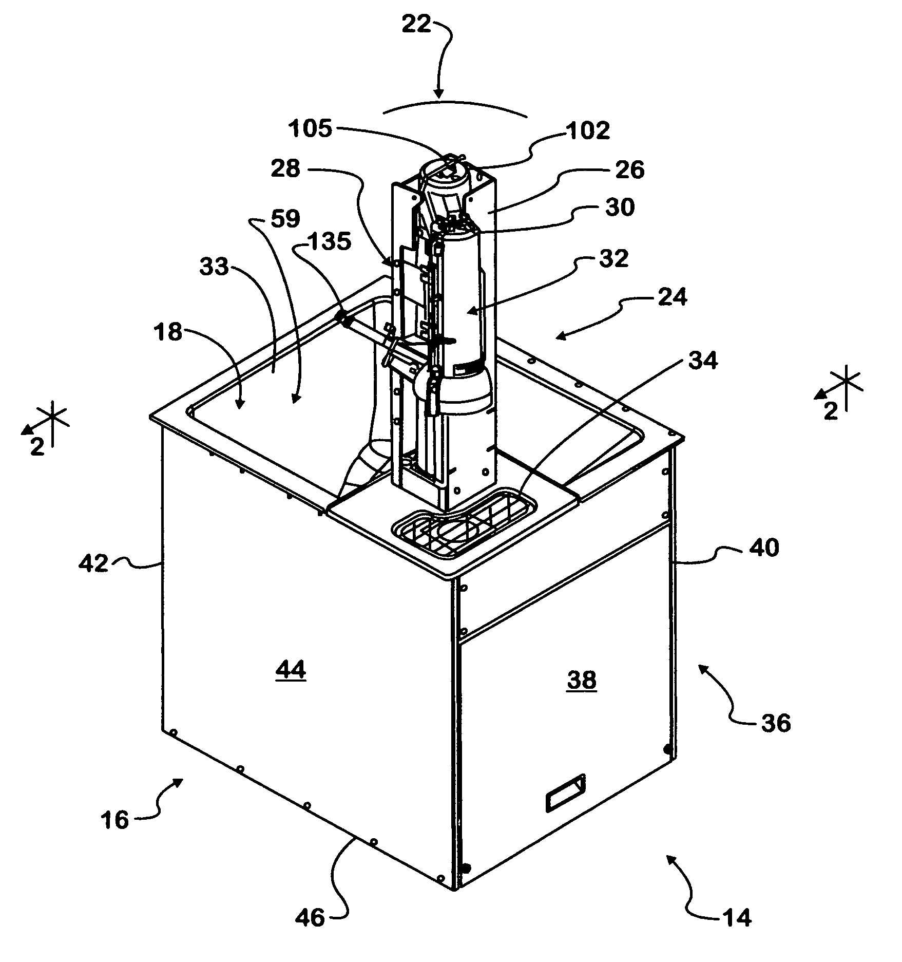
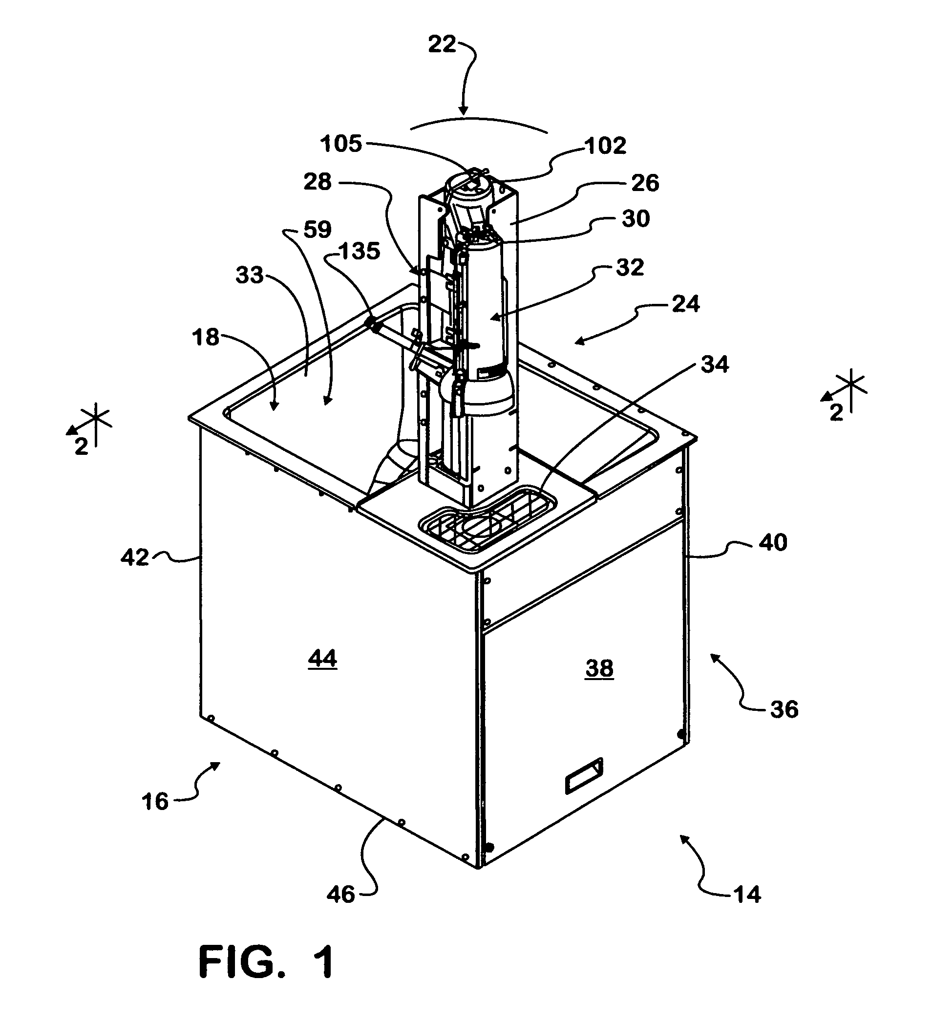
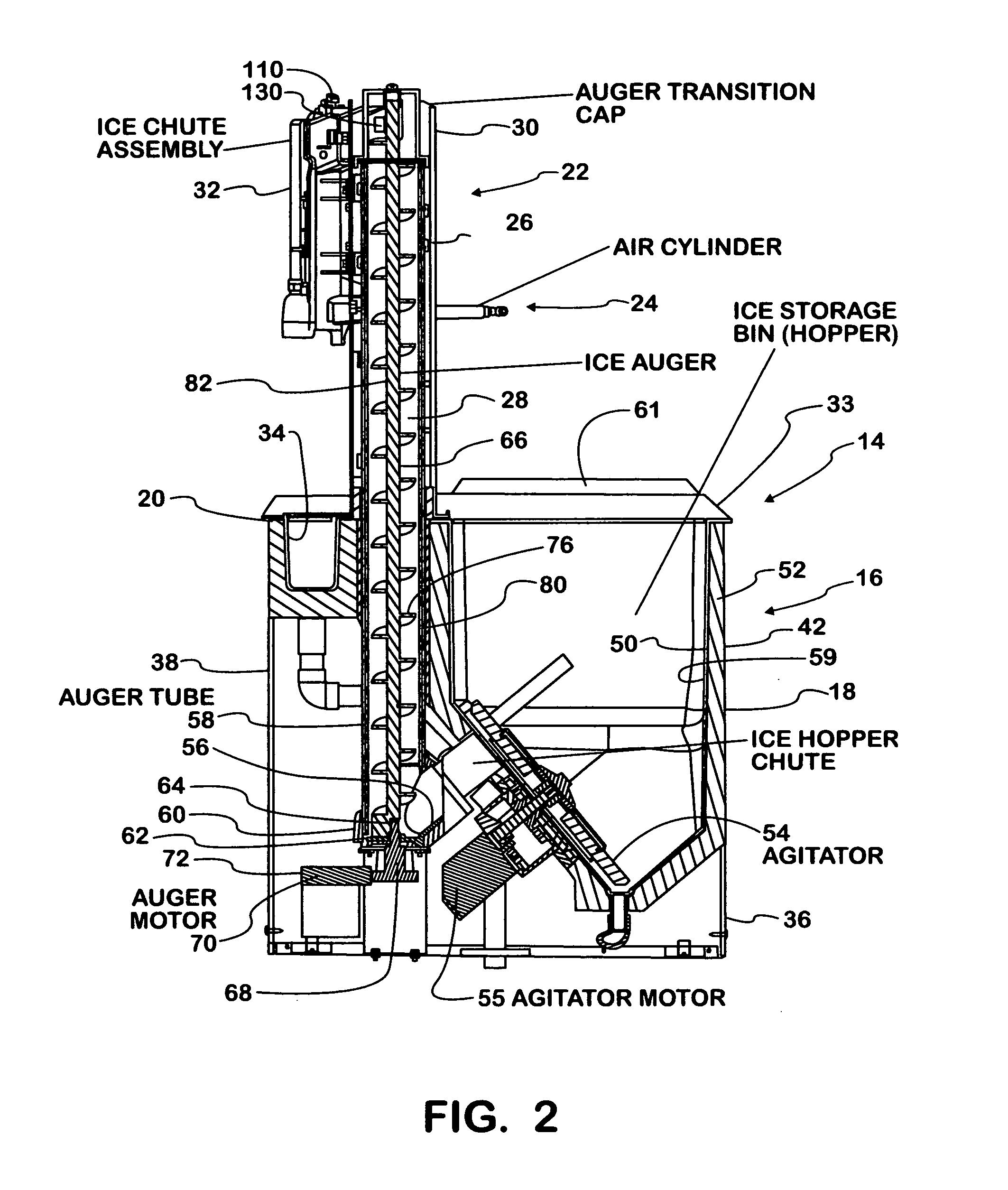
Referring to FIG. 1, an undercounter ice dispenser 14 is shown and comprises a lower portion 16 providing an ice bin 18 that is below the countertop level indicated by the arrow 20 (FIG. 20). The dispenser 14 also includes an upper portion 22 that rises above the counter level 20 and includes the upper portion 24 of a delivery means 26, in the form of an auger means 28. The auger means 28 delivers ice into the top 30 of an ice delivery chute 32. All of these components will be further described below. The counter 33 also contains a service drain area 34 wherein any spilt ice and ice melt water can be collected.

As shown more fully in FIGS. 1 and 2, the ice bin 18 is contained within a base or cabinet 36 including four sides 38, 40, 42 and 44, a bottom 46 and carries the countertop 33. The ice bin 18, itself, has an inner surface 50 made of non-rusting material, such as metal, aluminum, stainless steel or plastic. The exterior of these inner surfaces are covered with insulating materi...


PUM

PropertyMeasurementUnit
lengthaaaaaaaaaa
lengthaaaaaaaaaa
lengthaaaaaaaaaa

Abstract

An improved undercounter ice dispenser is disclosed that has a multiple piece auger made in sections for moving ice from the dispenser bin to its ice chute. The auger ice chute invention includes a sensor to reduce ice jamming and to detect when the ice chute is filled or needs filling and works in conjunction with a paddle on the auger to help make the transition. Proportional size ice quantities may also be selected via an interface and auger control.

Description

BACKGROUND OF THE INVENTIONHeretofore, it was known to dispense ice from an ice bin located underneath a service counter. The advantage of such configuration was the ice dispenser was located at the counter level, but the ice bin and related equipment could be located below the counter and out of sight, thus providing additional counter space. As is well known, counter space is a valuable commodity in a retail establishment, and any increase in counter space is of value. Such undercounter construction is known in the art. One way of bringing ice from the undercounter bin to the counter level dispenser was with an ice auger. Generally, this prior art auger was a one piece assembly (made unitary, such as machined from one piece of aluminum, or originally formed from several pieces and made unitary as by welding) which was from 3 to 5 feet in length, 4 feet being typical. The unitary auger construction was desired because of the loads imposed by the ice on the auger, and the length was...

Claims


Application Information

Patent Timeline
Patent Type & Authority Applications(United States)
IPC IPC(8): B67D7/08B67D7/62B67D7/58B23P19/04
CPCF25C5/002F25C5/187Y10T29/53Y10T29/49826G01F13/005F25C5/20
Inventor SEVCIK, E. SCOTTIVANCEVIC, DUSAN N.SANGUINET, ANDREW J.JABLONSKI, THADDEUS M.TOBLER, ANDREW J.TINUCCI, PETER S.DIFATTA, VINCENZO
Owner MARMON FOODSERVICE TECH INC
Why Eureka
Eureka Blog
Learn More