Method of measuring the velocity of an aircraft by laser doppler anemometry

Active Publication Date: 2011-02-24
THALES SA
View PDF2 Cites 13 Cited by
  • Summary
  • Abstract
  • Description
  • Claims
  • Application Information

AI Technical Summary

Benefits of technology

[0014]The invention provides a method of determining the velocity of an aircraft relative to a mass of air, which is precise, inexpensive, and reliable, or with a known reliability, and which is readily available, even when the aircraft is in an inhomogeneous mass of air.
[0054]The method according to an embodiment of the invention serves to improve the reliability of the measurement of the velocity of an aircraft when it is in a speed-inhomogeneous environment. More particularly, this method serves to improve the reliability of the measurement of the velocity of an aircraft in a cloudy environment or when at least one line-of-sight axis is directed towards the ground.
[0055]This method also makes it possible to increase the availability of the velocity measurement in a speed-inhomogeneous environment. It does not degrade the precision of the velocity measurement when the environment is homogeneous.
[0056]The method also allows the user system (the pilot or automatic flight system) receiving the information about the velocity of the aircraft to choose to use the velocity information or not, depending on the level of reliability of the information transmitted thereto.
[0057]The method according to the second embodiment of the invention helps to improve the reliability of the measurement of the velocity of an aircraft in an environment disturbed by vortex perturbations.

Problems solved by technology

However, when an aircraft moves through a mass of air which is speed-inhomogeneous (that is to say when there are several masses of air moving at different speeds), it is not possible to determine the components of the velocity vector on the line-of-sight axes reliably since it is sometimes impossible to determine a unique frequency in the spectra of the backscattered signals on the line-of-sight axes.
The conventional methods of determining the velocity of an aircraft have the drawback either of determining a velocity which may be false (the pilot being unaware that the value supplied to him is not reliable) or of not determining a velocity vector (the velocity of the aircraft is therefore not accessible).
A method based on a pulsed laser does not have these drawbacks, but this method is more expensive and less precise, for velocity measurements, than a method based on a continuous laser since the spectra resulting from the backscattered signals are spectrally more spread out.

Method used


Image

  • Method of measuring the velocity of an aircraft by laser doppler anemometry
  • Method of measuring the velocity of an aircraft by laser doppler anemometry
  • Method of measuring the velocity of an aircraft by laser doppler anemometry

Examples


first embodiment

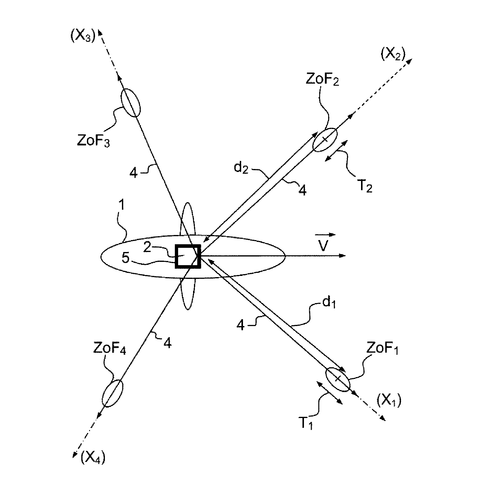
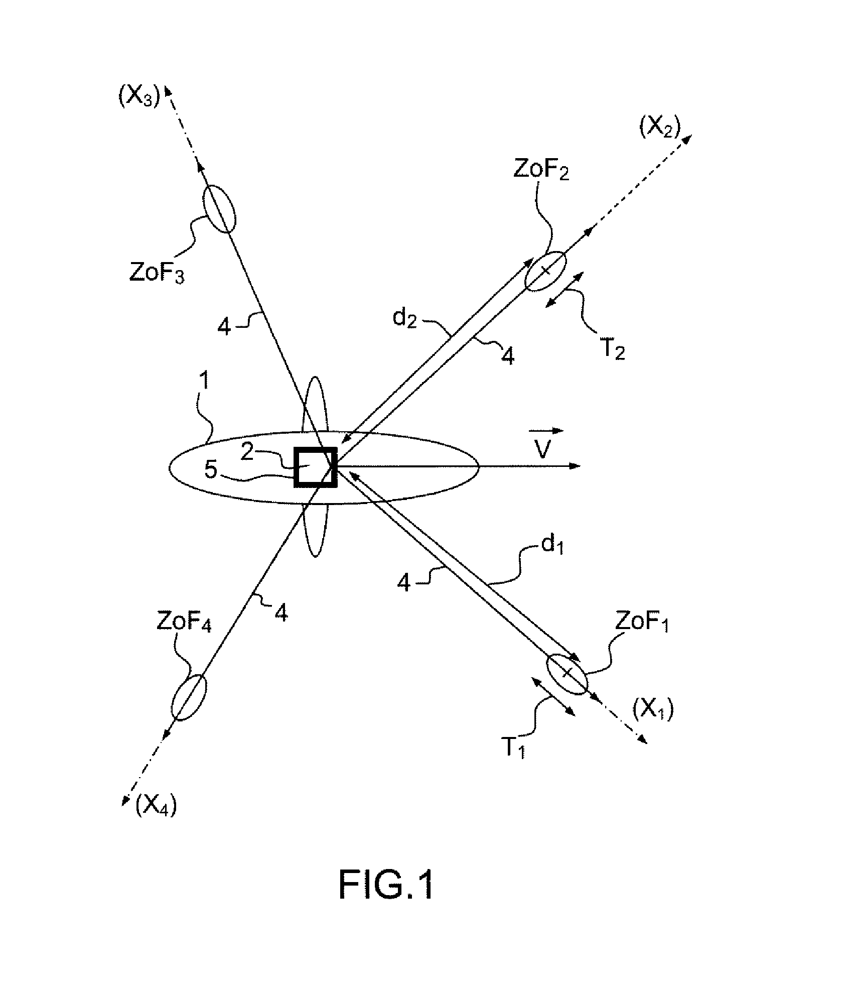
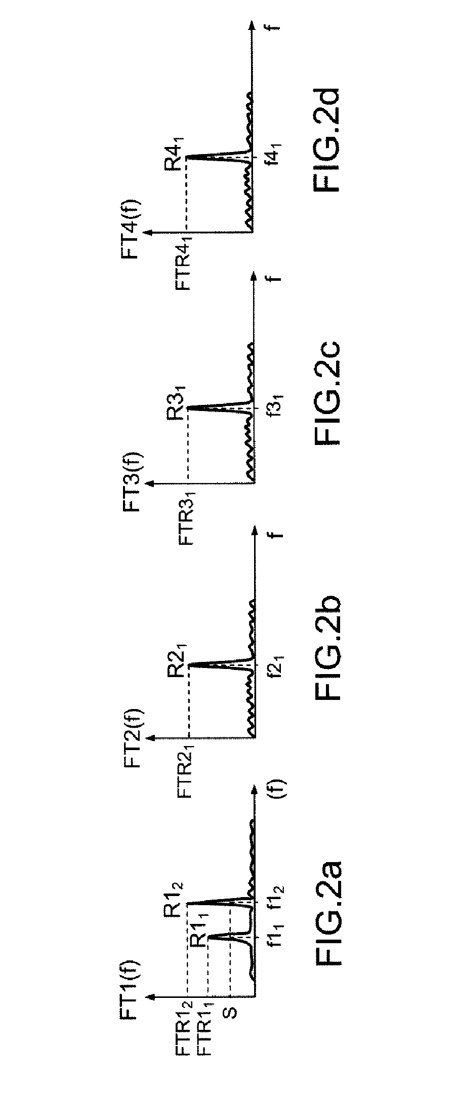
[0086]In a first embodiment according to the invention, the velocity vector {right arrow over (V)} is chosen by implementing the method described below. One or more lines on each of the line-of-sight axes X1, X2, X3, X4, are selected. A line is identified when it satisfies a predetermined line selection criterion. A line selection criterion may consist in identifying a line when the amplitude of the spectrum of the signal exceeds a predetermined threshold S. The spectrum is filtered by an operator matched to the expected signal, for example by a Gaussian having the characteristics corresponding to the expected turbulence of the mass of air.

[0087]A first line is identified at the frequency at which the amplitude of the filtered spectrum is a maximum and above the threshold S. The next line is determined by the same method after having removed, from the spectrum, a frequency range lying around the frequency of the first identified line. The line detection procedure stops when there ar...

second embodiment

[0119]In other words, the second embodiment amounts to selecting base axes that are line-of-sight axes on which at least one line has been identified and to constructing candidate vectors from the identified lines on these base axes.

[0120]In this embodiment, the calculation axes are the line-of-sight axes. The candidate vectors are projected on all the line-of-sight axes and an expected signal is optionally ascribed to each projection. Next, the consistencies CON of the candidate vectors are calculated, these being the products, effected on all the line-of-sight axes, of the individual consistencies of the vectors on each line-of-sight axis. The individual consistencies are calculated in the same way as in the first embodiment. The measured velocity vector is then obtained by carrying out a likelihood analysis optionally preceded by a weighting of the consistencies similar to the analysis carried out in the first embodiment.

[0121]In the first two embodiments, the candidate vectors a...

third embodiment

[0123]In a third embodiment according to the invention, the method is based on the fact that the velocity vector {right arrow over (V)} of the aircraft does not vary suddenly. The candidate velocity vectors {right arrow over (V)}c at a given instant t lie within an uncertainty volume, the boundary of which is defined according to the calculated velocity vector at the previous instant t−Δt. For example, the uncertainty volume is estimated from at least one previous velocity measurement by propagation, for example using a Kalman filter.

[0124]As a variant, the uncertainty volume is also estimated from information about the dynamics of the carrier (for example from inertial information delivering low-noise measurements). Thus, a better estimate of the uncertainty volume is obtained.

[0125]The uncertainty volume is divided into candidate velocity vectors, for example by means of one of the following two conventional methods:[0126]random sampling in the uncertainty volume (“particulate” me...


PUM


Abstract

Method of measuring the velocity of an aircraft at a given instant, by laser Doppler anemometry, by performing the steps of acquiring a backscattered signal on at least three oriented line-of-sight axes, and calculating the spectrum of the backscattered signal on each of the line-of-sight axes. Further, acquiring an additional backscattered signal on at least one additional line-of-sight axis (X4) not coincident with one of the three first line-of-sight axes (X1, X2, X3), and calculating the spectrum of the backscattered signal on the additional line-of-sight axis (X4). Several candidate velocity vectors ({right arrow over (V)}c) and of the projections of the candidate vectors on at least one line-of-sight axis (X1, X2, X3, X4) are calculated. The consistency of the candidate vectors ({right arrow over (V)}c) is calculated as a function of their projections and as a function of each spectrum of the corresponding backscattered signal on the respective calculation axis (X1, X2, X3, X4). The measured velocity vector ({right arrow over (V)}c) is chosen from among the candidate velocity vectors ({right arrow over (V)}c).

Description

FIELD OF THE INVENTION[0001]The invention relates to methods of measuring the velocity of an aircraft by laser Doppler anemometry by means of a Lidar (Light Detection and Ranging) in which the emission produced for example by a continuous laser (Light Amplification by Stimulated Emission of Radiation) is used.BACKGROUND[0002]Methods of measuring the velocity of an aircraft consists in measuring the frequency shift between an emitted reference wave and a wave backscattered by the natural aerosols in the air, which are used as velocity tracers, located on the line-of-sight axis. This shift is representative of the projection, on the line-of-sight axis, of the velocity of the aircraft relative to the air. To take reference measurements, the laser is generally focussed onto a focal zone chosen to be sufficiently far from the aircraft so that the mass of air contained therein is as little disturbed by the aircraft as possible. In this case, the backscattered wave emanates mainly from the...

Claims


Application Information

Patent Timeline
IPC IPC(8): G01P3/36
CPCG01S17/58G01P5/26
Inventor LACONDEMINE, XAVIERSCHLOTTERBECK, JEAN-PIERRERENARD, ALAIN
Owner THALES SA
Why Eureka
Try Eureka