
Sampler linearity by simultaneous derivative sampling

a derivative sampling and linear sampling technology, applied in the field of linear sampling of samplers by simultaneous derivative sampling, can solve the problems of degrading linearity of samplers at high input signal frequencies, method suffers from digital complexity and power consumption,

Inactive Publication Date: 2011-02-24
INTERSIL INC
View PDF5 Cites 3 Cited by
  • Summary
  • Abstract
  • Description
  • Claims
  • Application Information

AI Technical Summary

Benefits of technology

[0007]An embodiment of an analog to digital converter described herein provides sampler linearity at high signal frequencies.
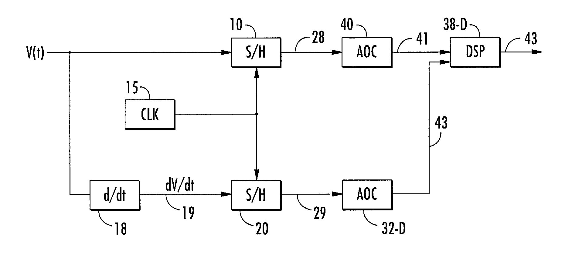
[0008]This is achieved through simultaneous sampling of both the input signal V(t) and input derivative signal dV / dt, with the latter generated by an analog circuit. The resulting simultaneous analog samples of the derivative are then used to correct non-linearity in the sampler by analog, digital, or mixed-signal signal processing circuits and / or programmed processes. Direct analog measurement of dV / dt at the very same sample instants as when the samples of V(t) are taken provides a more accurate input to such correction algorithms.
[0009]One possible way to acquire analog samples is to employ a second sampler operating simultaneously with the primary (input voltage) sampler. This second sampler takes as input an analog signal proportional to dV / dt of the input signal. A capacitor-resistor (C-R) network can provide such a signal proportional to the derivative in some instances, and may be sufficient for the needed correction depending upon input signal bandwidth. More elaborate circuits, either passive circuits or involving op-amps or other active circuitry, may provide improved dV / dt signals over a larger bandwidth.
[0014]The advantages are (1) simplicity (2) potentially very low power and (3) on unambiguous dV / dt estimate (e.g., one that does not depend on apriori knowledge of the signal's frequency content).

Problems solved by technology

However, these samplers sometimes suffer from degraded linearity at high input signal frequencies.
This method suffers from digital complexity and power consumption, and from the necessity of assumptions and constraints regarding the input signal spectrum—specifically, an assumption is made concerning which Nyquist zone the input signal occupies.

Method used


Image

  • Sampler linearity by simultaneous derivative sampling
  • Sampler linearity by simultaneous derivative sampling
  • Sampler linearity by simultaneous derivative sampling

Examples


Embodiment Construction

[0023]A description of example embodiments follows.

[0024]FIG. 1 is a block diagram of an Analog to Digital Converter (ADC) that uses direct analog measurement of dV / dt at sample instants of an input signal, V(t) to provide input to correct sample errors. In this first embodiment, a primary sampler 10 provides samples of the input signal, V(t), to be processed by a main analog to digital converter (ADC) core 40. Derivative information is acquired by employing a second sampler 20 operating simultaneously (e.g., using a common clock signal15) with the primary (voltage-sampling) sampler 10. The input to sampler 20 is an analog signal 19 that is proportional to dV / dt of the input signal, V(t). A simple capacitor-resistor (C-R) network 18 can provide such an analog derivative signal 19 over a reasonable bandwidth, and may be sufficient for the needed correction. More elaborate circuits 18, either passive or involving op-amps or other active circuitry, may provide a more accurate dV / dt est...


PUM


Abstract

A circuit for improved sampler linearity, in an analog to digital converter, by taking simultaneous analog samples of an input signal V(t) and its derivative, dV / dt. The correction can be implemented as a memoryless non-linear model in the analog, digital, or mixed signal domains. Delay elements placed in the clock signal path or main input signal path can provide more precise control over the correction.

Description

RELATED APPLICATIONS[0001]This application claims the benefit of U.S. Provisional Application No. 61 / 308,851, filed on Feb. 26, 2010 and U.S. Provisional Application No. 61 / 219,978, filed on Jun. 24, 2009. The entire teachings of the above application(s) are incorporated herein by reference.BACKGROUND[0002]Switched-capacitor samplers of the general type used in, for example, the KAD5512P-50 12-bit, 500 Mega-Sample Per Second (MSPS) Analog-to-Digital Converter (ADC) available from Intersil Corporation can provide high performance and low-power consumption. However, these samplers sometimes suffer from degraded linearity at high input signal frequencies. Such high-frequency non-linearities can arise due to an input signal V(t) having a high derivative, (dV / dt).[0003]One way in which a high input signal dV / dt can corrupt operation of such circuits is by imperfect bootstrapping of a series input switch that connects the sampler input to a plate (“top plate”) of a sampling capacitor. Ano...

Claims


Application Information

Patent Timeline
Patent Type & Authority Applications(United States)
IPC IPC(8): H03M1/06H03M1/12
CPCH03M1/12H03M1/0612
Inventor ANTHONY, MICHAEL P.
Owner INTERSIL INC
Learn More