
Coiled assembly for supporting the wall of a lumen

a technology of ophthacoil and lumen, which is applied in the field of mechanical devices, can solve the problems of loss of flexibility of coil, limited drug loading capacity of ophthacoil, and inability to achieve maximum drug output, etc., and achieves good supporting function, improved fatigue behavior, and improved flexibility.

Inactive Publication Date: 2011-02-17
HANSSEN INVESTMENT & CONSULTANCY
View PDF6 Cites 33 Cited by
  • Summary
  • Abstract
  • Description
  • Claims
  • Application Information

AI Technical Summary

Benefits of technology

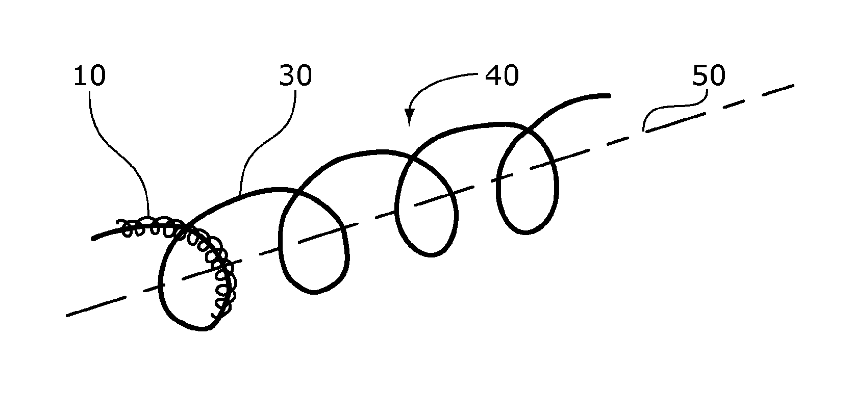
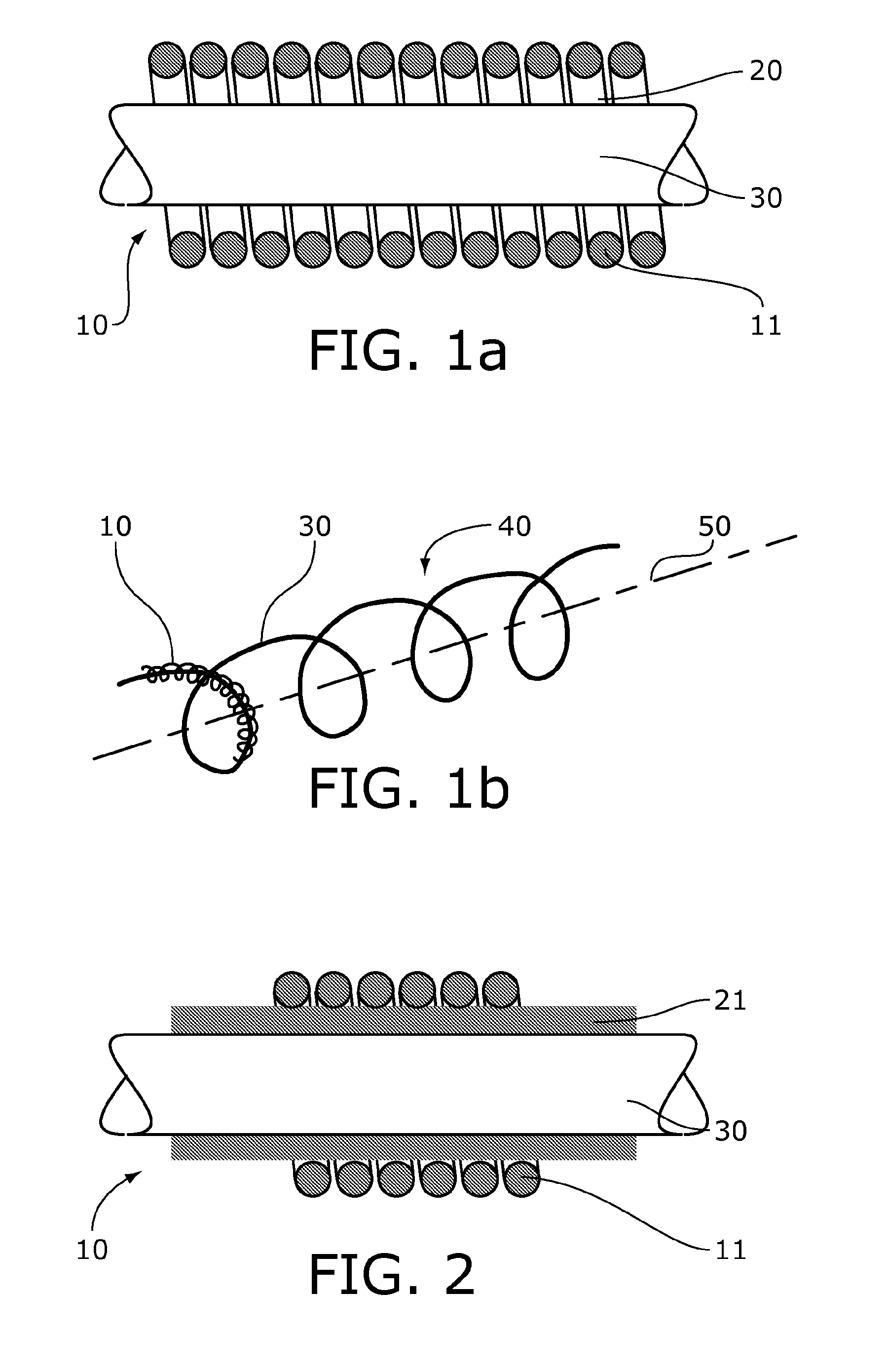
[0017]The invention relates to an improved device for supporting the wall of a lumen. A device according to the invention has an improved flexibility, improved fatigue behavior and a good supporting function. The invention accordingly provides a device for supporting the wall of a lumen comprising a coiled structure (10) defining an inner core (20) wherein the inner core comprises a support wire (30) comprising a shape memory material, wherein the shape memory material is programmed to make the coiled structure (10) assume a macro-coiled structure (40).

Problems solved by technology

There is a limitation, however, to the thickness of the active layer and therefore to the possible maximum drug output.
The drug loading capacity of the OphthaCoil is very limited however.
When polymerizing a hydrogel in the lumen itself, it appeared that the coil lost its flexibility.
The loss of flexibility is detrimental for the patient, since the device is no longer tolerated in the eye when rigid.
Particular disadvantage of such devices is that commonly used materials, such as shape-memory materials show symptoms of fatigue, making such devices less suitable for implantation at sites exposed to mechanical stress.
Such doubly coiled helical devices made of shape memory material would then run a considerable risk of breaking and thereby damage the artery or blood vessel wall.

Method used


Image

  • Coiled assembly for supporting the wall of a lumen
  • Coiled assembly for supporting the wall of a lumen
  • Coiled assembly for supporting the wall of a lumen

Examples


example

[0085]A straight superelastic Nitinol wire with a diameter of 0.2 millimeter and a length of 2.5 meter (Fort Wayne Metals) was coiled into the desired shape around a mandrel, heated to 480 degrees Celsius for 10 minutes and left to cool. This programs the wire to assume the structure defined by the mandrel.

[0086]A straight stainless steel 304V wire of 50 micrometer diameter (Fort Wayne Metals) was coiled on a mandrel to obtain a spring with an internal diameter of 0.3 millimeter and a length of 40 centimeters.

[0087]If desired, the Nitinol wire was coated with a drug according to standard techniques, basically as described in Hanssen et al., J. Biomed. Mater. Res. 48: 820-828 (1999) which is hereby incorporated by reference herein.

[0088]The Nitinol wire was hung vertically and straightened by weight at its bottom end, and the stainless steel spring was slid over the Nitinol wire. The device was cut into the appropriate length and the Nitinol wire was linked to the coiled structure us...


PUM


Abstract

The invention is in the field of mechanical devices. It relates to a device and methods for supporting the wall of a lumen. In particular, the invention relates to a device and method for supporting the wall of a human or animal body lumen, the device comprising a coiled body which can be inserted into a lumen and expand therein. The device may advantageously be used for treating arterial and vascular diseases, in particular coronary conditions and cardiovascular diseases. The device may also advantageously be used for the localized delivery of drugs. In particular, the invention provides a device for supporting the wall of a lumen comprising a coiled structure (10) defining an inner core (20) wherein the inner core comprises a support wire (30) comprising a shape memory material, wherein the shape memory material is programmed to make the coiled structure (10) assume a macro-coiled structure (40) upon an appropriate trigger.

Description

FIELD OF THE INVENTION[0001]The invention is in the field of mechanical devices. It relates to a device and methods for supporting the wall of a lumen. In particular, the invention relates to a device and method for supporting the wall of a human or animal body lumen, the device comprising a coiled body which can be inserted into a lumen and expand therein. The device may advantageously be used for treating arterial and vascular diseases, in particular coronary conditions and cardiovascular diseases. The device may also advantageously be used for the localized delivery of drugs.BACKGROUND OF THE INVENTION[0002]Coiled wires, suitable for keeping a body lumen open have been described. U.S. Pat. No. 6,086,547 describes a coiled guide wire for medical use, in particular for diagnostic purposes such as catheterization. During the diagnostic examination the guide wire is introduced into for example the patient's vascular system, and the smooth outer surface of the guide wire ensures that ...

Claims


Application Information

Patent Timeline
IPC IPC(8): A61F2/82
CPCA61F2/88A61F2210/0076A61F2250/0067
Inventor HANSSEN, JOHANNES HENDRIKUS LEONARDUSBESSELINK, PETRUS ANTONIUS
Owner HANSSEN INVESTMENT & CONSULTANCY
Learn More