Switchgear and Method for Operating Switchgear
a switchgear and switchgear technology, applied in the direction of switchgear arrangement, high-tension/heavy-dress switch, air-break switch, etc., can solve the problems of low environmental conformity, complex configuration, large number of components, etc., and achieve the effect of reducing the siz
- Summary
- Abstract
- Description
- Claims
- Application Information
AI Technical Summary
Benefits of technology
Problems solved by technology
Method used
Image

Examples
first embodiment
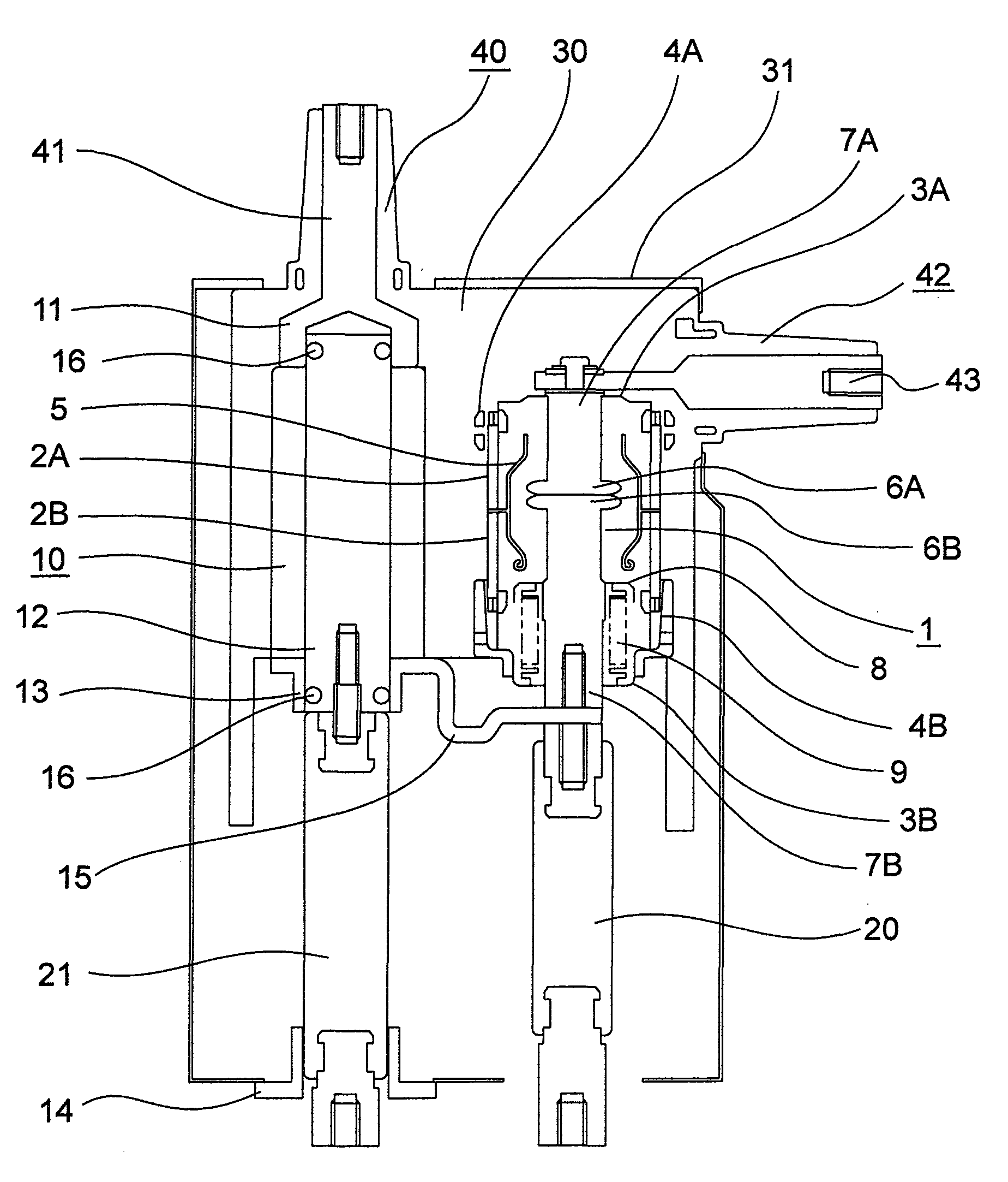
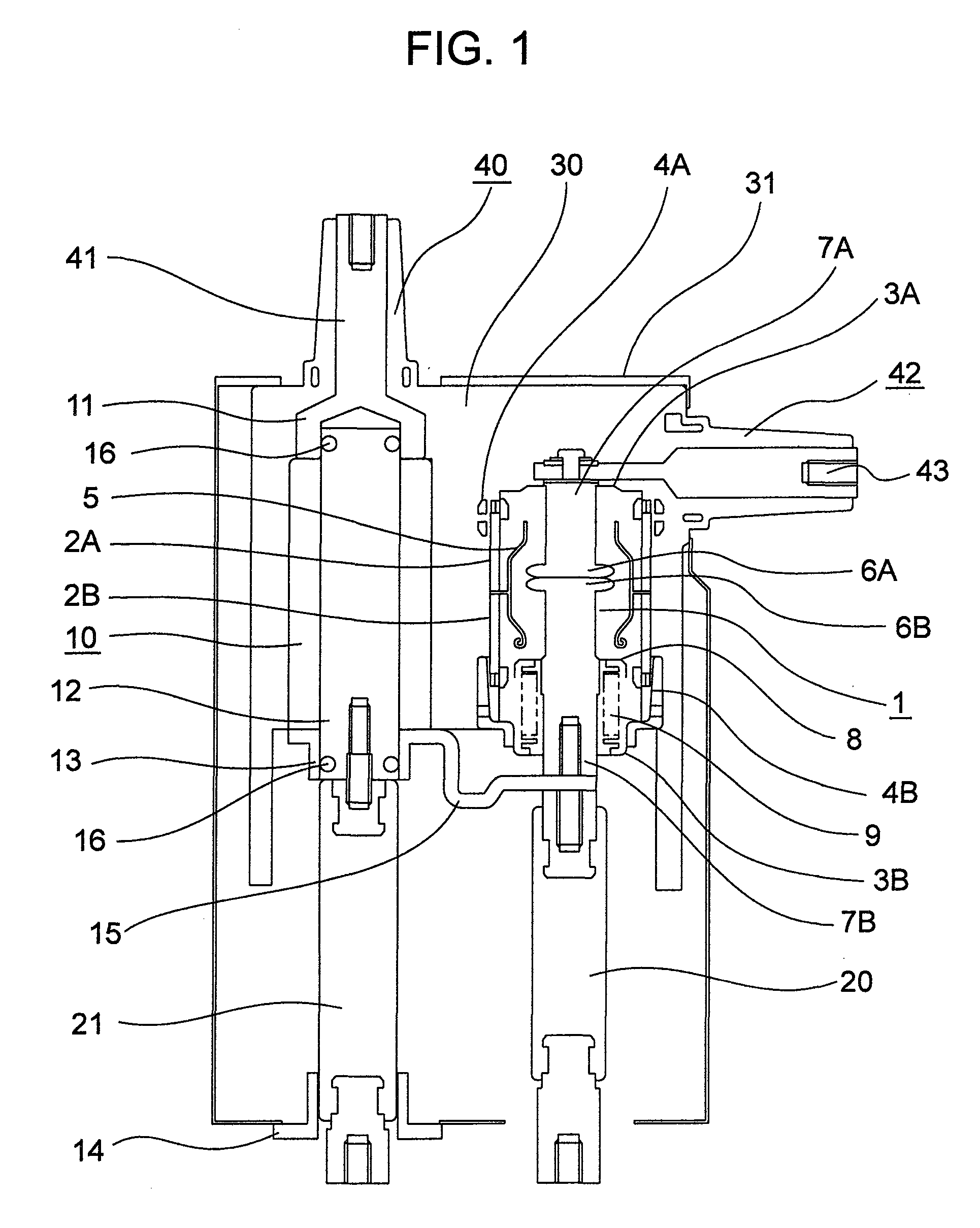
[0036]Hereinafter, a switchgear of the present invention will be described with reference to FIGS. 1 to 6. A switch unit of the switchgear in the present embodiment is comprised of a vacuum valve 1, an earthing and disconnecting switch 10, a bus bushing 40 and a cable bushing 42, which are provided in an earthed metal container 31 and are integrally casted with a solid insulator 30 of epoxy or the like.
[0037]The vacuum valve 1 has a fixed side electrode 6A, a movable side electrode 6B, a fixed side holder 7A connected to the fixed side electrode 6A, a movable side holder 7B connected to the movable side electrode 6B and an arc shield 5 for protecting a ceramics insulating cylinder from arc, arranged in a vacuum container comprised of a fixed side ceramics insulating cylinder 2A, a movable side ceramics insulating cylinder 2B, a fixed side end plate 3A and a movable side end plate 3B. The fixed side holder 7A is connected to a cable bushing center conductor 43 so that power can be su...
second embodiment
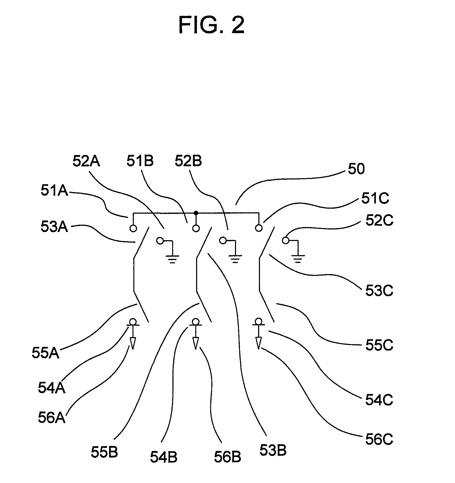
[0063]An operation of the switchgear of the present invention as is configured above will be described with reference to FIGS. 12 to 15.
[0064]In FIG. 12, the first bushing side fixed electrode 11 corresponds to an earthing and disconnecting switch fixed contacts 51A. The first movable electrode 12 of the earthing and disconnecting switch corresponds to an earthing and disconnecting switch movable contact 53A. The first earthing side fixed electrode 14 corresponds to an earthing and disconnecting switch earthing contact 52A. The fixed side electrode 6A of the vacuum valve 1 corresponds to a current switch section fixed contact point 54A. A cable head 56A is connected to the cable bushing 42. Further, a second bushing side fixed electrode 11A corresponds to an earthing and disconnecting switch fixed contact 51B. A second movable electrode 12A of the earthing and disconnecting switch corresponds to an earthing and disconnecting switch movable contact 53B. A second earthing side fixed e...
third embodiment
[0071]FIGS. 17 and 18 show an example of configuring the switch device for one phase out of a three-phase AC three-circuit switch device unit using the The earthing and disconnecting switches 10A, 10B and 10C, vacuum valves 1A, 1B and 1C, flexible conductors 15A, 15B and 15C and the like are collectively casted with the solid insulator 30, and cable bushings 42A, 42B and 42C are also casted at the same time. Collective casing leads to reducing the amount of the mold material as a whole, and then reducing the cost.
[0072]Further, in the present embodiment, the switch unit of the same phase can be integrally molded, and therefore, the number of castings can be reduced.
PUM
 Abstract
Description
Claims
Application Information
 - R&D
- Intellectual Property
- Life Sciences
- Materials
- Tech Scout
- Unparalleled Data Quality
- Higher Quality Content
- 60% Fewer Hallucinations
Browse by: Latest US Patents, China's latest patents, Technical Efficacy Thesaurus, Application Domain, Technology Topic, Popular Technical Reports.
© 2025 PatSnap. All rights reserved.Legal|Privacy policy|Modern Slavery Act Transparency Statement|Sitemap|About US| Contact US: help@patsnap.com