
Process for wrapping loads, in particular palletised loads, and relative system

a technology for palletised loads and wrapping loads, applied in the field of wrapping loads, can solve the problems of significant increase in manufacturing, installation and maintenance costs, and complexity from both a structural and functional perspective, and achieve the effects of reducing overall transportation costs, reducing costs, and reducing costs

Active Publication Date: 2011-02-10
E80 GRP SPA
View PDF23 Cites 17 Cited by
  • Summary
  • Abstract
  • Description
  • Claims
  • Application Information

AI Technical Summary

Benefits of technology

The main aim of this invention is to provide a process and system for wrapping loads, in particular palletised loads, that allow loads that have to be transported to be wrapped practically, easily, quickly and functionally and, at the same time, considerably reducing the overall transportation costs in terms of less expense for assembly, installation, maintenance and running of the wrapping system.
Another object of this invention is to provide a process and system for wrapping loads, in particular palletised loads, that make it possible to overcome the mentioned drawbacks of the known technique as part of a simple, rational, easy, effective use and low cost solution.

Problems solved by technology

Such wrapping stations do, however, have some drawbacks, among which is the fact that they are rather complex and complicated from both a structural and functional point of view.
In this regard, the fact is emphasized that the need for movement means on the wrapping head to move it near to and away from the palletised, load entails some considerable difficulties and complications, both during the assembly phase and when the wrapping stations are working, leading to a notable increase in manufacturing, installation and maintenance costs.

Method used


Image

  • Process for wrapping loads, in particular palletised loads, and relative system
  • Process for wrapping loads, in particular palletised loads, and relative system
  • Process for wrapping loads, in particular palletised loads, and relative system

Examples


Embodiment Construction

Reference will now be made in detail to the present embodiments of the present invention, examples of which are illustrated in the accompanying drawings, wherein like reference numerals refer to the like elements throughout. The embodiments are described below in order to explain the present invention by referring to the figures.

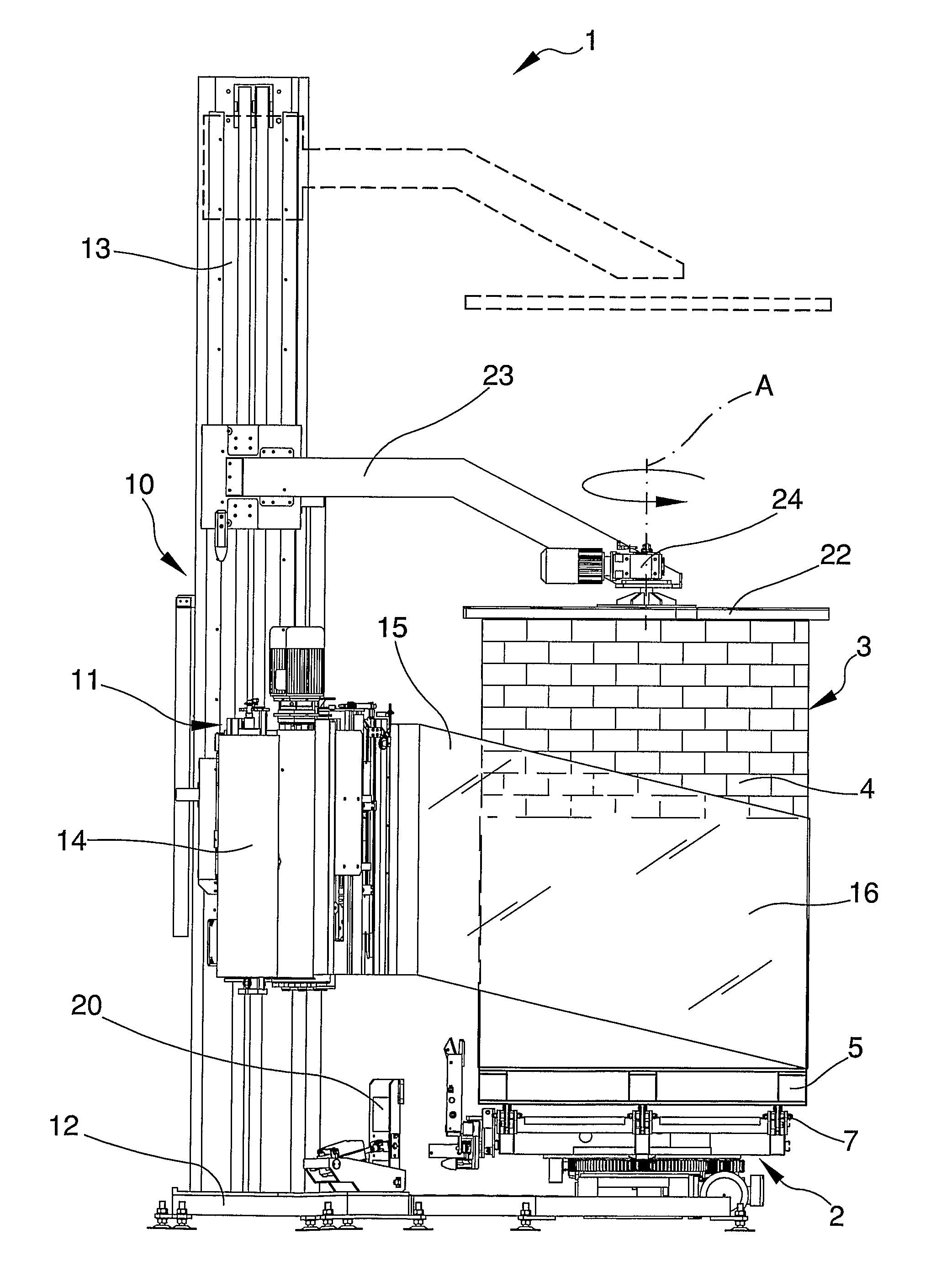
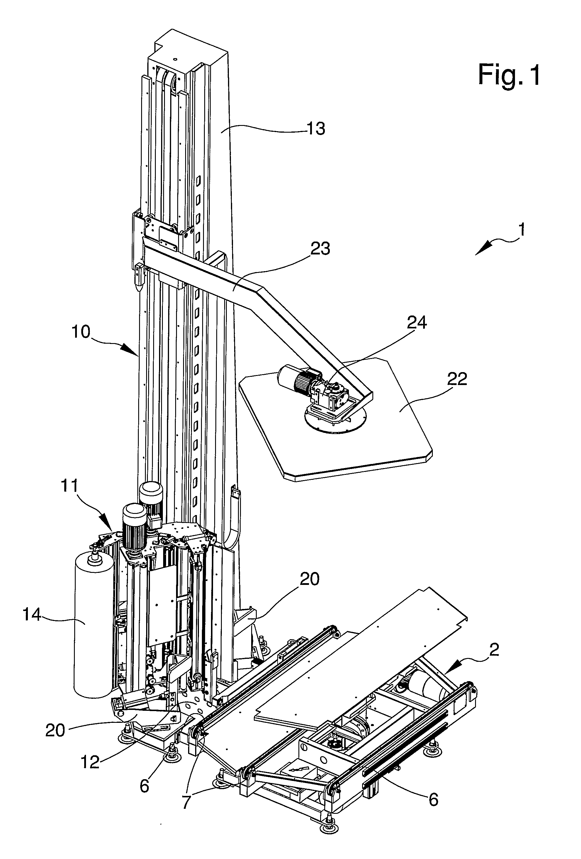
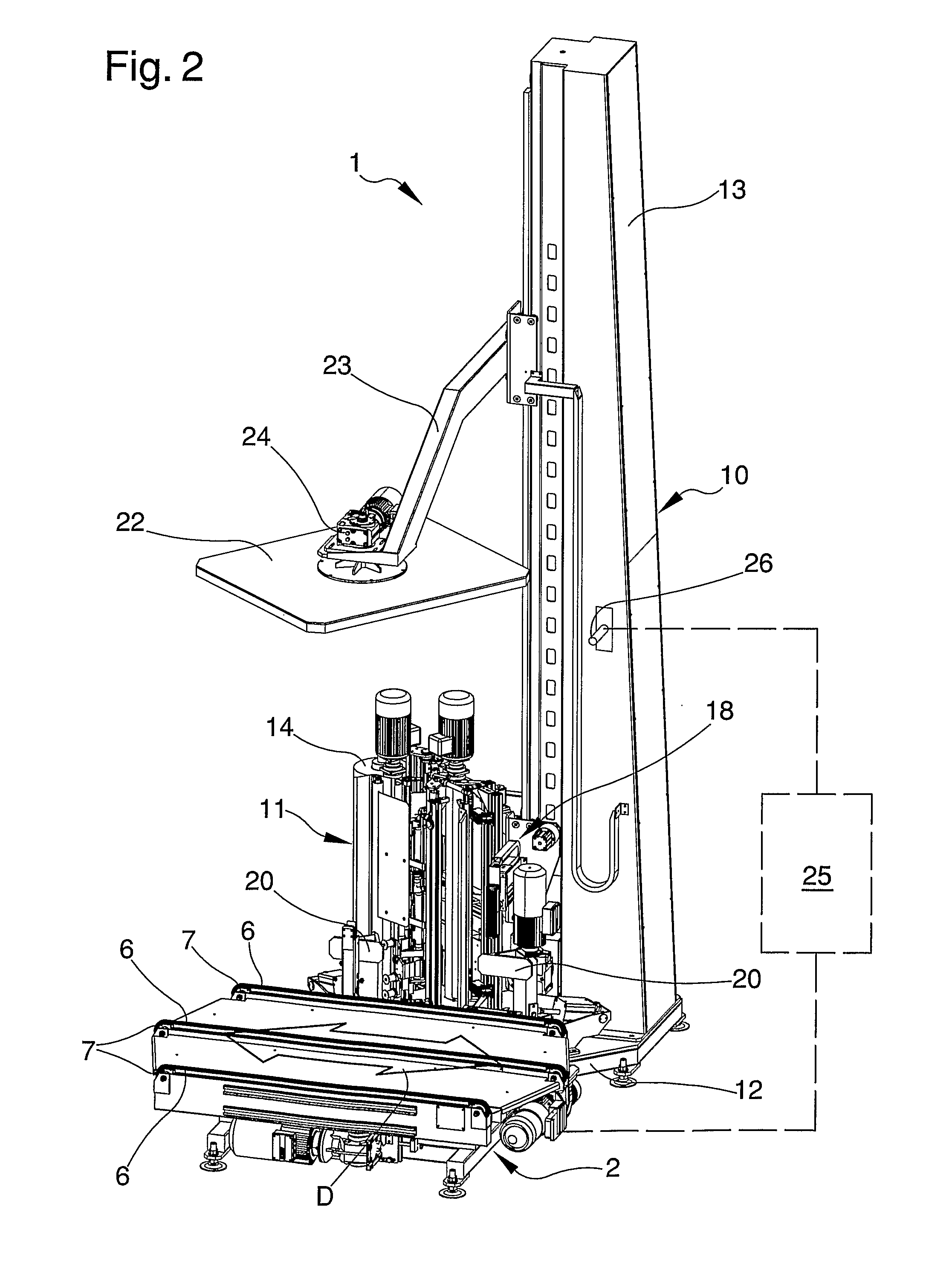
With particular reference to such figures, a system for wrapping loads, in particular palletised loads, has been globally indicated by 1.

The system comprises a rotating platform 2 which is suitable for receiving a load 3 to be wrapped and making the load rotate around a vertical rotation axis A.

In the particular embodiment of the invention illustrated in the figures, the load 3 is the palletised type and consists of one or more goods or items 4 loaded on a pallet 5; however, it is noted that the system 1 can also be used to wrap non palletised loads 3.

Advancement means 6, 7, suitable for moving the load 3 in an advancing direction D, are mounted on the rotat...


PUM


Abstract

The process for wrapping loads, in particular palletised loads, comprises the following phases:providing a rotating platform that is suitable for receiving a load to be wrapped and which has advancement means for advancing the load in an advancing direction, and a movement machine for moving a wrapping head along a substantially vertical direction for co-operating with the rotating platform to wrap the load with a covering sheet, the wrapping head having cutting means for cutting the covering sheet to form a cut end, and joining means for connecting the cut end to the load;placing the load to be wrapped on the rotating platform;wrapping the load on the rotating platform with the covering sheet to define a stabilising wrap;turning the rotating platform so the advancing direction is towards the wrapping head;advancing the wrapped load on the rotating platform in the direction approaching the wrapping head until located in proximity to the head itself; and thencutting the covering sheet to form a cut end;joining the cut end to the wrapped load.

Description

BACKGROUND OF THE INVENTION1. Field of the InventionThis invention refers to a process for wrapping loads, in particular palletised loads, and to a system for implementing the method.2. Description of the Related ArtAs is common knowledge, palletised loads consist of one or more goods distributed in a more or less orderly manner on a pallet so it can be moved and transported in a practical and easy way.The palletised loads are normally covered with a stabilising wrap that immobilises the loads on the pallet so the loads can then be transported without any risk of falling or tipping over.The usual way to make such stabilizing covering is to tightly wrap the sides of the load and pallet with a plastic covering film that is unwound from a dispensing reel.Wrapping is normally done by means of either automatic or semi automatic wrapping stations, which use one or more machines, intended to move a wrapping head which supports the reel of plastic film.In a particular type of wrapping stati...

Claims


Application Information

Patent Timeline
IPC IPC(8): B65B11/04
CPCB65B11/045B65B57/10B65B35/24B65B35/22B65B11/04B65B11/58
Inventor MURAROTTO, EMILIO
Owner E80 GRP SPA
Learn More