
Programmable watch winding apparatus

Inactive Publication Date: 2011-02-03
CHANG
View PDF13 Cites 11 Cited by
  • Summary
  • Abstract
  • Description
  • Claims
  • Application Information

AI Technical Summary

Benefits of technology

[0008]One objective of the present invention is to provide a programmable watch winding apparatus that winds a mechanical watch by rotating the mechanical watch in a predetermined direction by a predetermined number of turns, and prevents the mechanical watch from over-winding or under-winding.
[0009]Another objective of the present invention is to provide a programmable watch winding apparatus that buffs mechanical resonance so as to operate with less operational noise and protect a mechanical watch carried thereon from vibration-induced damage.
[0010]Another objective of the present invention is to provide a programmable watch winding apparatus that is equipped with cushion components for protecting reduction gears in a transmission device thereof from being damaged when imposed with an outward reverse force or an additional co-rotating force excessively accelerating rotation thereof.
[0011]Another objective of the present invention is to provide a programmable watch winding apparatus that implements a control unit to control a number of winding turns and stop operating when a predetermined number is reached so as to ensure the mechanical watch wound sufficiently and eliminate over-winding and under-winding.

Problems solved by technology

However, the rotational rate of a motor in the orbital watch-winding apparatus may be subject to the changeable supply voltage and unlikely to remain constant.
Consequently, the number of turns performed by the orbital watch-winding apparatus during a preset time period cannot be accurately controlled and thus the watch may be over-wound or under-wound.
Besides, operational vibration of the orbital watch-winding apparatus may damage the apparatus itself or the watch thereon.
In addition, the mechanism may be damaged when the mandrel receives an outward force counter to its rotational direction or an additional co-rotating force excessively accelerating rotation of the mandrel.
However, the prior art provides no approach to addressing the problems.

Method used


Image

  • Programmable watch winding apparatus
  • Programmable watch winding apparatus
  • Programmable watch winding apparatus

Examples


Embodiment Construction

[0021]While a preferred embodiment provided hereinafter for illustrating the concept of the present invention as described above, it is to be understood that the components of the embodiment shown in the accompanying drawings are depicted for the sake of easy explanation and need not to be made in scale.

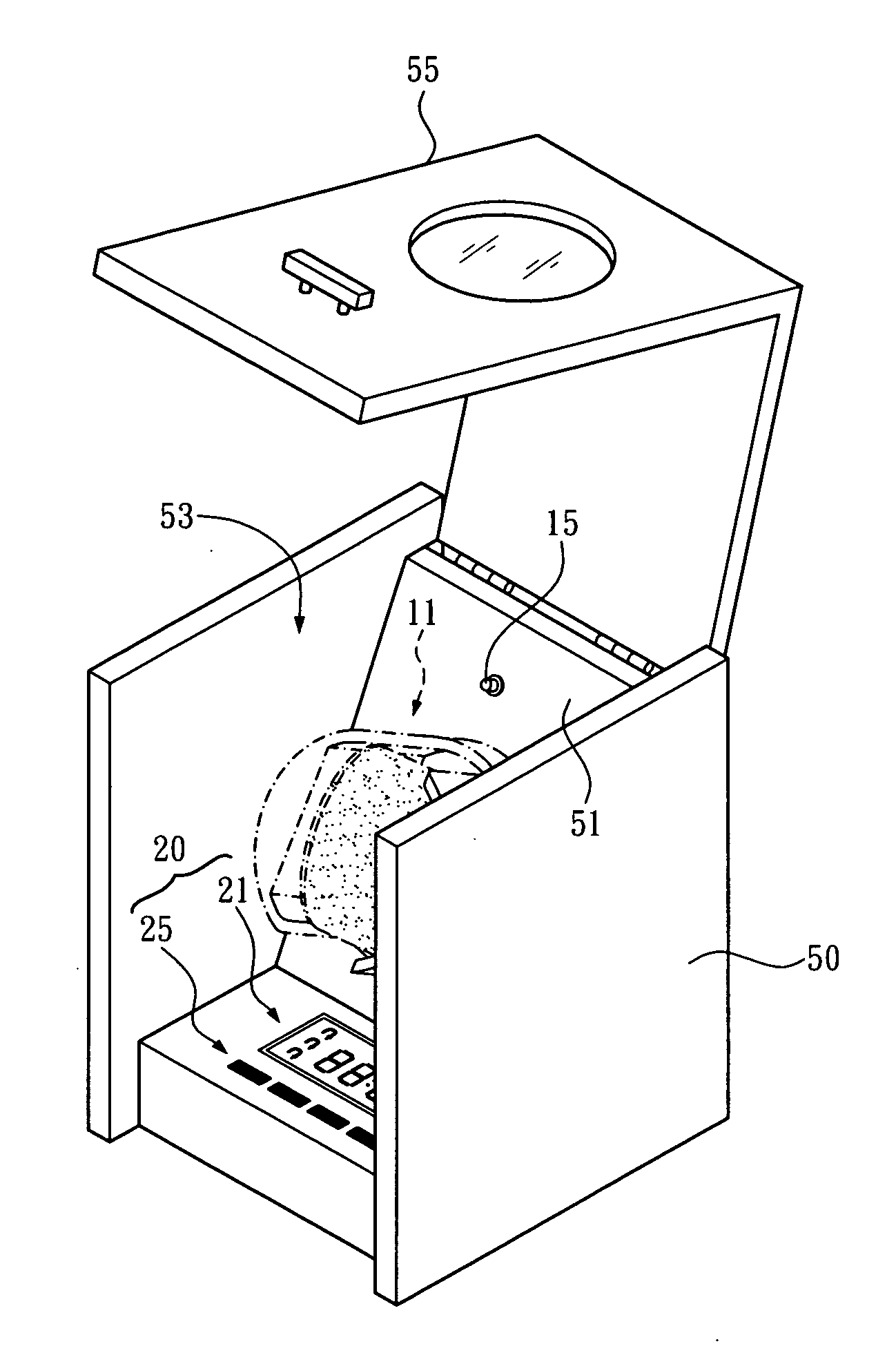
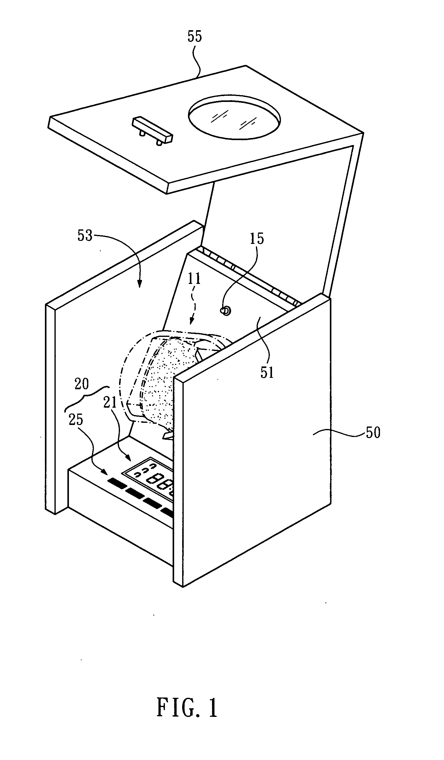
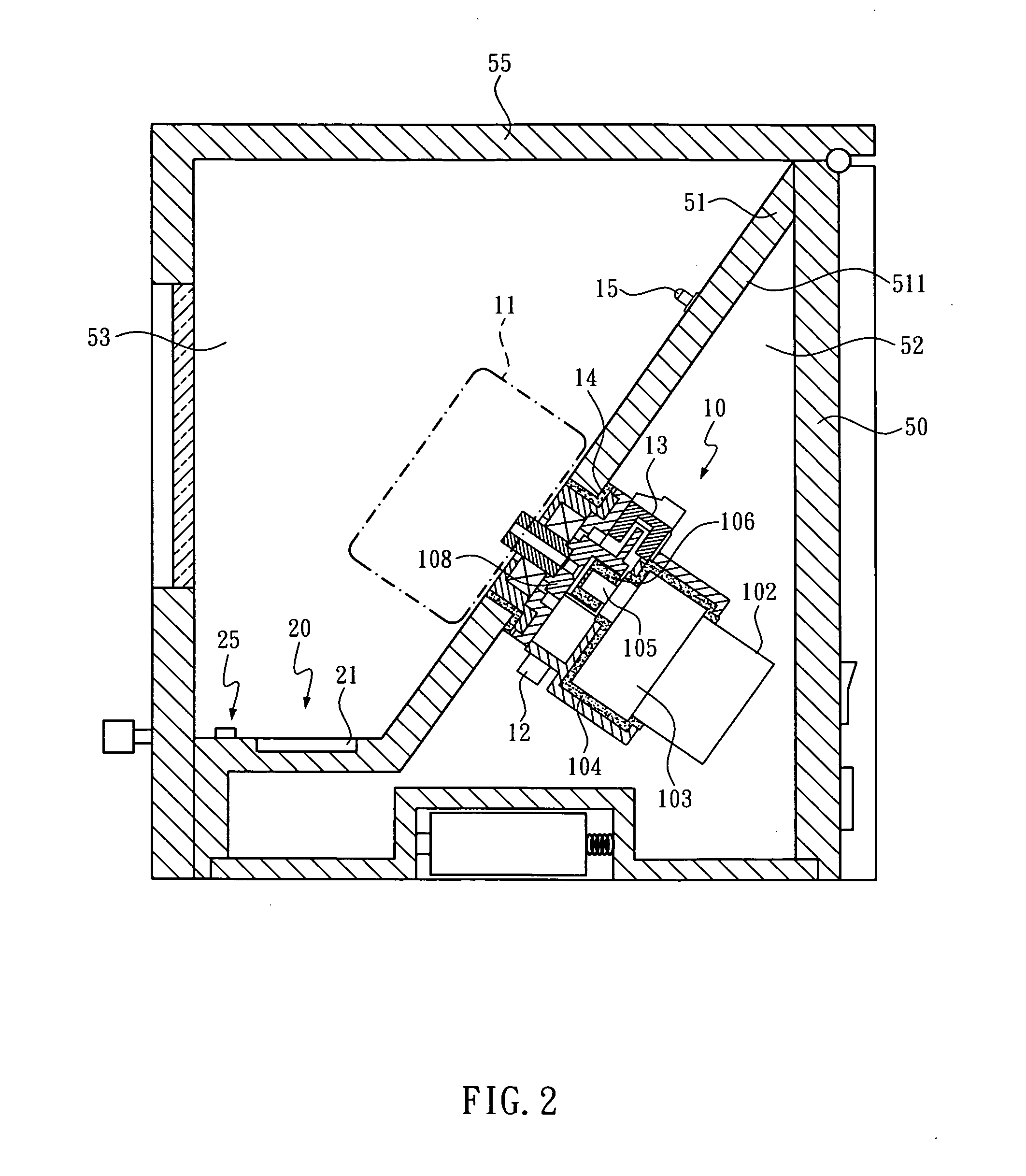
[0022]Please refer to FIGS. 1 and 2 for a programmable watch winding apparatus of the present invention. The programmable watch winding apparatus includes a box 50, a gear motor 10, a rotatory base 11, a sensor 12, a user interface 20, and a control unit 30.

[0023]The box 50 has an inclined partition 51 that separates the box 50 into an inward part 52 and an outward part 53. The box 50 is provided with a liftable cover 55 that serves to close the outward part 53 when affixed to the box 50.

[0024]The transmission device 10 is fixed to an inner surface 511 of the partition 51 and positioned in the inward part 52. A driving shaft 101 of the transmission device 10 pierces through the parti...


PUM


Abstract

A programmable watch winding apparatus includes a user interface for users to input a winding number and rotational direction of turns the programmable watch winding apparatus performs to wind a mechanical watch, and a control unit controlling a transmission device to rotate a rotatory base according to the users' input. Thereby, the programmable watch winding apparatus is fully controlled to automatically wind the mechanical watch carried thereon.

Description

BACKGROUND OF THE INVENTION[0001]1. Technical Field[0002]The present invention relates to a watch winding apparatuses for automatically winding mechanical watches. More particularly, the present invention relates to a programmable watch winding apparatus that autumnally winds mechanical watches in a fully controlled manner.[0003]2. Description of Related Art[0004]A watch winding apparatus is designed for automatically winding mechanical watches. Mechanical watches are wound by kinetic energy created from human hands' movement. Watch winding apparatuses have thus been developed for performing particular operation to substitute for human hands and keep mechanical watched wound during periods of non-use.[0005]A known orbital watch-winding apparatus is disclosed in U.S. Pat. No. 6,254,270. The orbital watch-winding apparatus includes a base unit and a mandrel rotatably mounted to the base unit. A watch is supported on the outer surface of the mandrel. When activated, the watch moves in ...

Claims


Application Information

Patent Timeline
IPC IPC(8): G04B5/00
CPCG04D7/009
Inventor CHANG, SHIH-TSUNG
Owner CHANG
Learn More