
Automatic dispenser

a dispenser and automatic technology, applied in the field of automatic dispensers, can solve the problems of affecting the affecting the safety of the ejection device, and the delivery of articles, so as to achieve the effect of simple detection of the movement simple operation of the ejection device, and accurate and reliable determination

Inactive Publication Date: 2011-02-03
CROSS TECH
View PDF7 Cites 11 Cited by
  • Summary
  • Abstract
  • Description
  • Claims
  • Application Information

AI Technical Summary

Benefits of technology

"The present invention is an automatic dispenser that uses a magnetic sensor and an overcurrent protection device to detect the movement of the ejection device. This allows the dispenser to accurately and reliably determine if an article has been delivered correctly and prepare for the next delivery operation. The invention does not require long, complex and awkward wirings inside the vending machine and provides protection against anomalous electric conditions. It can be used for articles dispensers and doses dispensers, such as powder coffee or granulated materials."

Problems solved by technology

A first drawback of such a solution is that the microswitch may bounce back to some extent when abruptly pressed and released, thus causing wrong detections of the rotation of the geared motor and therefore of the advance of the articles, hence leading to article delivery problems.
A second drawback of such a solution is that the ejection assembly sometimes gets stalled or braked due to an anomalous positioning of the articles to be delivered; such anomalous positioning may occur when the articles are being loaded into the dispenser or, more often, during the operation of the dispenser, in particular during the actuation of the ejection assembly; this causes article delivery problems as well as damage to the electric motor of the geared motor, which is stalled or braked just when power is being supplied to it—this anomalous condition of the electric motor may cause even worse material and personal damage.
However, if the ejection assembly is not stalled, but is only braked, the fault will not be detected and risks of damage will result.

Method used


Image

  • Automatic dispenser
  • Automatic dispenser
  • Automatic dispenser

Examples


Embodiment Construction

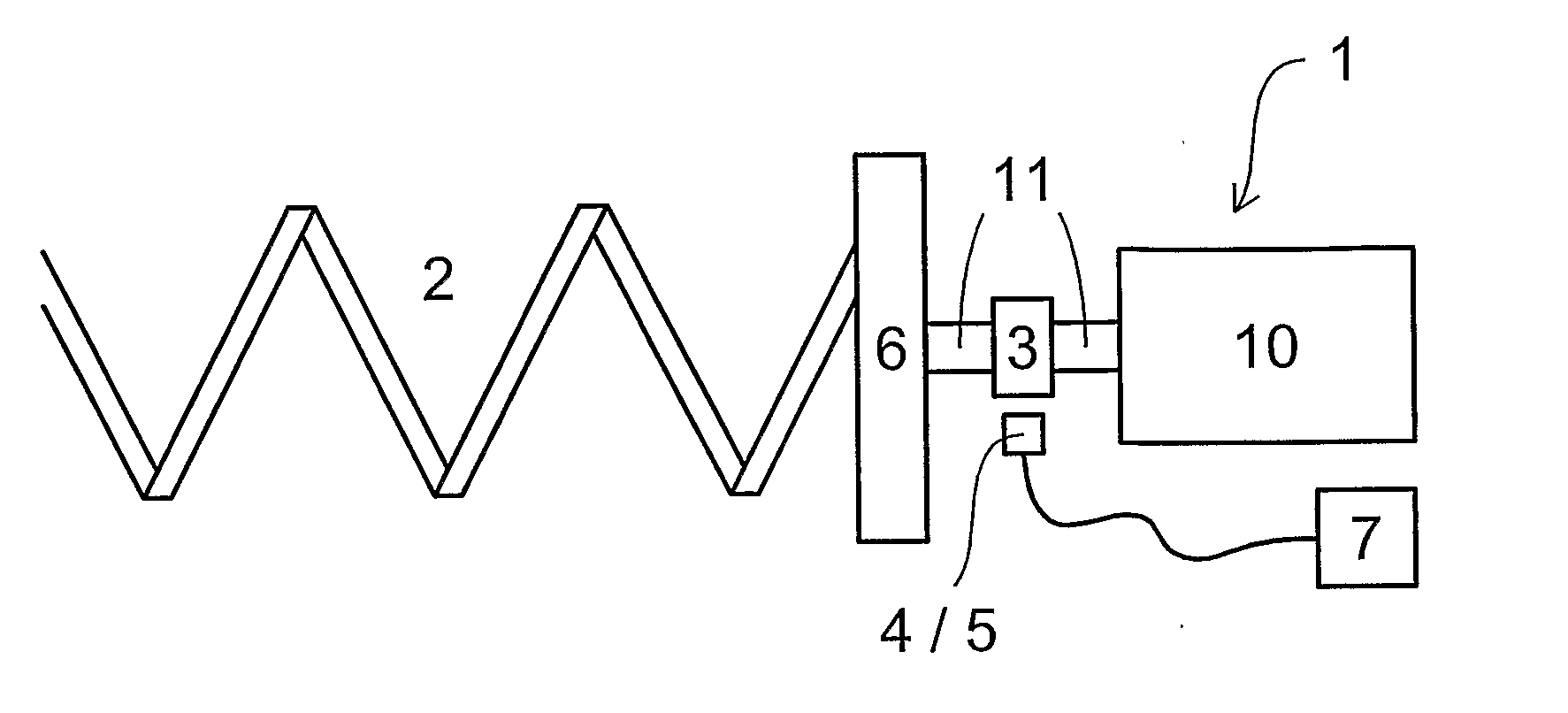
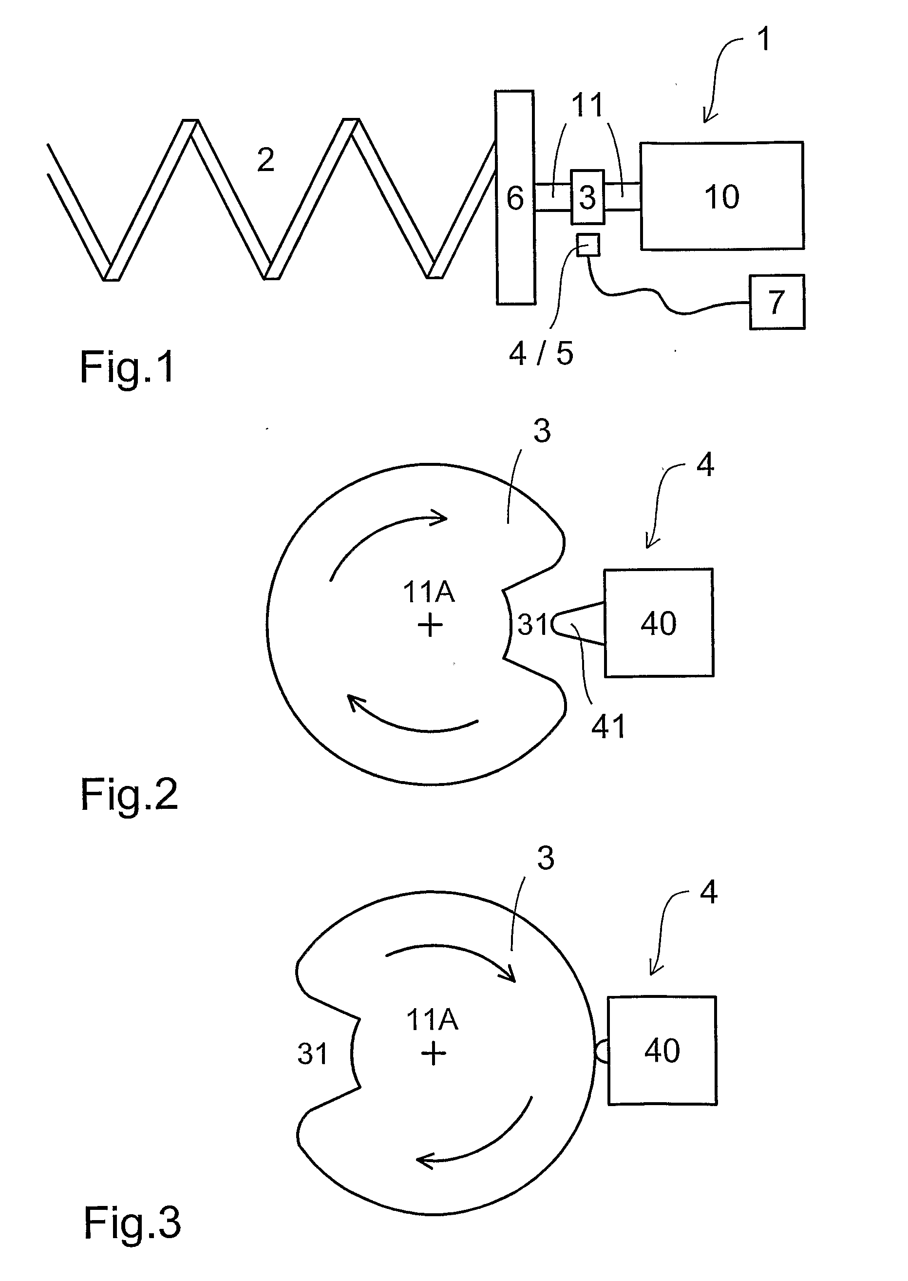
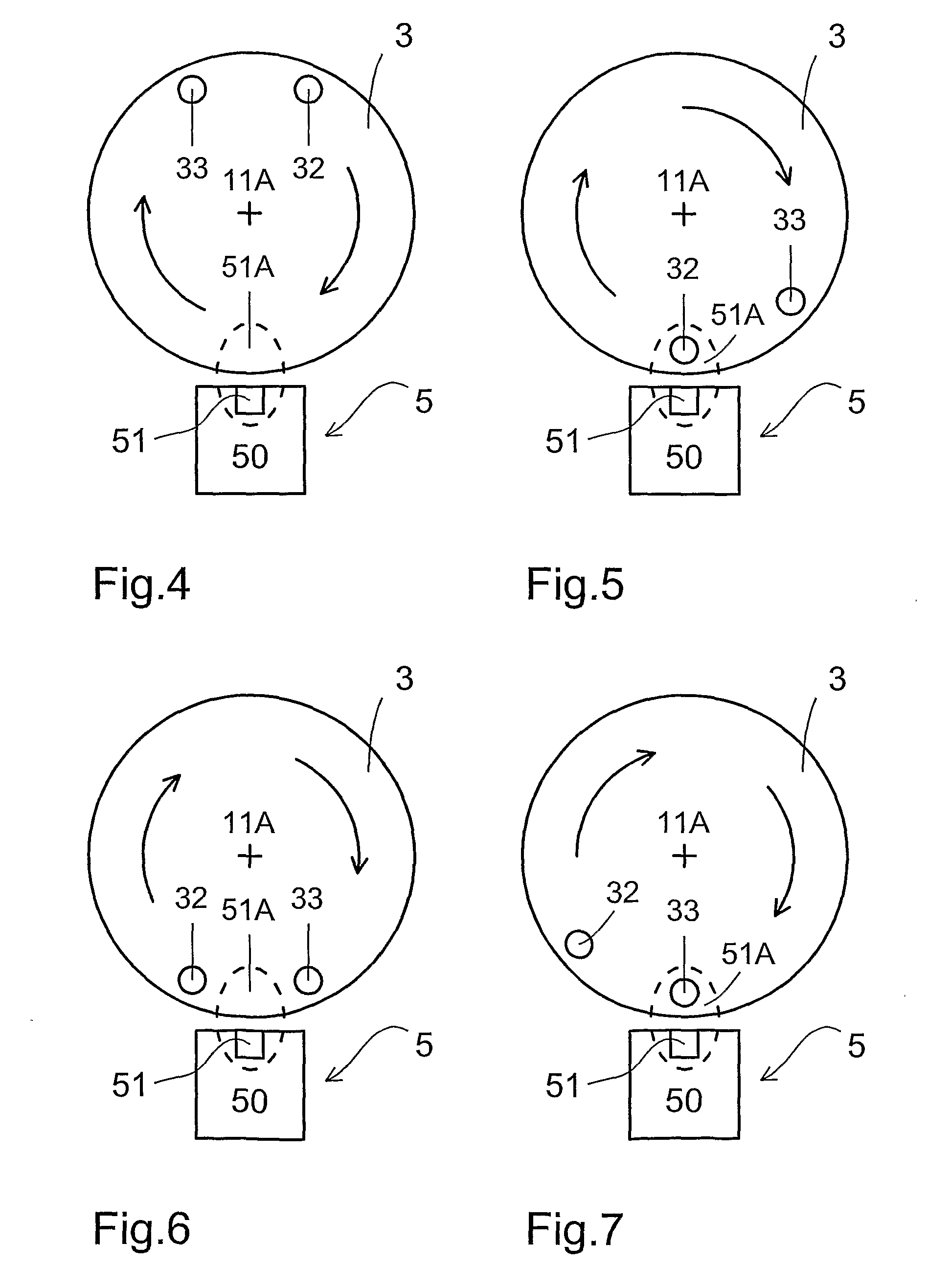
[0036]The present invention will now be described with reference to FIG. 1 as well as to FIG. 4, FIG. 5, FIG. 6, FIG. 7 and FIG. 8.

[0037]The automatic dispenser according to the present invention is equipped with an ejection assembly; said assembly comprises at least:

[0038]a geared motor (1 in FIG. 1),

[0039]an ejection device (2 in FIG. 1) fitted either directly or indirectly to the output shaft (11 in FIG. 1) of the geared motor (1 in FIG. 1),

[0040]detection means (3 and 5 combined together in FIG. 1) configured to detect the movement of the ejection device (2 in FIG. 1); the detection means comprise:

[0041]at least one magnet (32 and / or 33 in FIG. 4, FIG. 5, FIG. 6 and FIG. 7) associated with the output shaft (11 in FIG. 1) of the geared motor (1 in FIG. 1),

[0042]at least one magnetic sensor (5 in FIG. 1) positioned in a manner such as to detect when said at least one magnet (32 and / or 33 in FIG. 4, FIG. 5, FIG. 6 and FIG. 7) passes through a predetermined region (51A in FIG. 1),

[0...


PUM


Abstract

The present invention relates to an automatic dispenser equipped with an ejection assembly which includes at least a geared motor, an ejection device fitted to the output shaft of the geared motor, and detection means configured to detect the movement of the ejection device, wherein the detection means includes at least one magnet associated with the output shaft of the geared motor, and at least one magnetic sensor positioned in a manner such as to detect when the magnet passes through a predetermined region; and the ejection assembly further includes an overcurrent protection device connected electrically upstream of the geared motor.

Description

CROSS REFERENCE TO RELATED APPLICATIONS[0001]This application claims benefit under 35 U.S.C. §371 to international application No. PCT / IB2008 / 003571, filed Dec. 22, 2008.BACKGROUND OF THE INVENTION[0002]1. Field of Invention The present invention relates to an automatic dispenser.[0003]2. Background Art[0004]A typical application of the present invention is the field of articles automatic dispensers that are commonly called “vending machines” are used for dispensing, upon payment, various types of products, in particular foods and beverages. The present description will refer in particular to the field of articles dispensers, even though the present invention is not limited to such an application.[0005]Articles automatic dispensers equipped with an articles ejection assembly are currently available on the market; said assembly comprises at least a “geared motor” (i.e. a unit incorporating an electric motor and a motion reduction mechanism), a metal spiral fitted to the output shaft ...

Claims


Application Information

Patent Timeline
Patent Type & Authority Applications(United States)
IPC IPC(8): B65H3/16
CPCG07F11/00G07F11/42
Inventor MARINBENETELLO, ANDREA
Owner CROSS TECH
Learn More