Maintenance platform for wind turbines

Inactive Publication Date: 2011-02-03
LOTT KENNETH SKOVBO
View PDF12 Cites 23 Cited by
  • Summary
  • Abstract
  • Description
  • Claims
  • Application Information

AI Technical Summary

Benefits of technology

[0026]The aim of the design presented here is to produce a working or maintenance platform suspended on cables, wherein said platform can be used as universally as possible, especially offshore, and is able during operation to provide greatly differing workspaces with ease and without constructional changes.
[0039]A maintenance platform of this kind removes the inability of previously existing suspended access equipment to adapt flexibly to different work pieces whose perpendicular cross-sectional projection changes considerably over the path traveled by the platform. As a result, the personnel is able to perform work simultaneously at any time on different parts of the work piece.
[0040]In one preferred variant of the invention, the maintenance platform has five sub-platforms connected to each other by swivel joints. This configuration leads to the maintenance platform almost fully enclosing the workspace, thus enabling access from all sides to a rotor blade to be maintained. The enclosed configuration also increases the stability of the maintenance platform, of course. By inserting intermediate segments in each single platform before work begins, it is also easy to move up and down rotor blades. In one advantageous variant of the invention, the sub-platforms are configured so that they can be enlarged by inserting intermediate segments.
[0041]In order to adjust the sub-platforms, a drive is preferably provided for each degree of freedom, said drive connecting sub-platforms in such a way, for example, that the sub-platforms can be swiveled in the working plane relative to each other with the aid of the drive. The drive provided for swiveling the sub-platforms is preferably a spindle drive that connects the sub-platforms with each other and is disposed relative to the swivel joint connecting said sub-platforms in such a way that the sub-platforms can be swiveled in the working plane relative to each other with the aid of the spindle drive. Alternatively, the drive can also be disposed in the swivel joints themselves. Overall, a maintenance platform with at five sub-platforms and at four swivel joints connecting said sub-platforms enables a five-bar linkage to be realized that permits variable inner contours to be achieved and thus enabling the maintenance platform to be easily adjusted during operation to different cross-sectional profiles.
[0048]The present construction is also rendered suitable for use by virtue of suspension from at least two points, of which at least one is attached to the hub in front of the rotor plane by means of the cable suspension member. The cable suspension member rotates with the rotor, without the support and safety cable rotating as well. This prevents the cables from twisting.

Problems solved by technology

The increasing size of wind turbines, not only with respect to hub height, but also to the specific dimensions of the blades, combined with the desire for offshore wind power generation gives rise inevitably to requirements for suspended access equipment that cannot be met or fully met with the construction designs that have existed hitherto.
The disadvantage of suspending the access equipment from the rotor blades themselves is that, in order to treat the next rotor blade, the suspended access equipment must be dismounted and remounted again after the rotor has been rotated to the next position.
If repair work needs to be carried out in sections where the mounting for the suspended access equipment is located, this type of mounting is unfavorable.
Since maintenance and repair work on blades mainly involves lamination and painting work, dismounting and remounting suspended access equipment cannot be carried out until after full hardening, for example of the paint finish, in the area of the mounting.
Current suspended access equipment that is not suspended from the rotor blades themselves, but from the machine house instead have the disadvantage that, although the rotor can still be turned while the suspended access equipment is mounted, it is necessary to release the tension in guy lines to the ground.
What is common to all solutions hitherto is that the suspended access equipment lacks the flexibility to adapt to changes in the cross-sectional profile of the workpiece (in this case the blades) during operation.
The consequence is that the rotor blades can be treated very well in the flange area or in the upper third next to the hub, whereas work becomes increasingly difficult to perform the closer one gets to the blade tip.
The reason for this is the increasing gap between the rotor blade or workpiece surface and the closest front handrail of the suspended access equipment, which is limited to a major extent by the distance that personnel can reach.
Even with such an arrangement, it is a time-consuming process to carry out a cleaning of the rotor blades of a windmill, just as such a known arrangement would probably require the use of machinery, such as a crane, for fixation of the suspension means.
Further, the platform itself will have a considerable weight and size, thereby leading to further costs and use of heavy machinery for lifting and lowering the platform.
Devices of corresponding kind are encumbered with the same disadvantages as those mentioned above, including that extensive use must be made of special material such as cranes, for example mobile cranes, or relatively comprehensive materials which, for example, are mounted on the turbine tower beforehand.
These prior art systems are generally not configured in a manner facilitating user-friendliness and do not provide the personnel with an optimal safety environment.

Method used


Image

  • Maintenance platform for wind turbines
  • Maintenance platform for wind turbines
  • Maintenance platform for wind turbines

Examples


Embodiment Construction

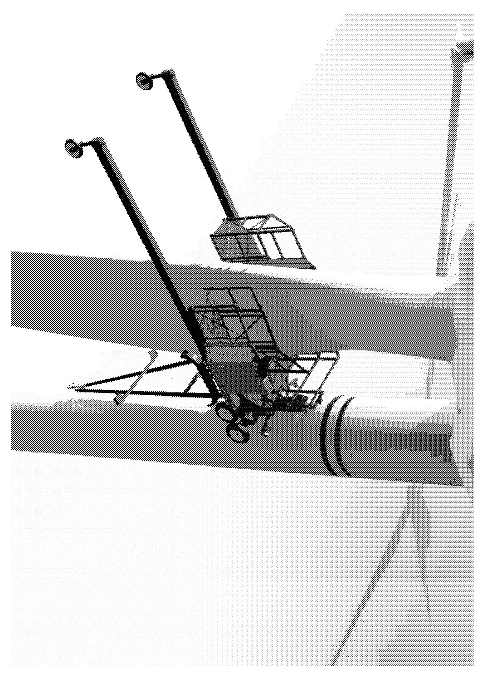
[0049]The wind turbine shown in FIG. 1 comprises a tower, a horizontally swivelable nacelle mounted on the top end of tower and a rotor which is rotatable about a horizontal axis and mounted inside the nacelle. Rotor comprises three rotor blades attached to a common hub.

[0050]A maintenance platform of the present invention is suspended from nacelle and hub by means of support cables (not shown). One of said support cables is attached to the hub by means of a cable suspension member, while additional support cables are attached to nacelle. The maintenance platform, support cables and cable suspension member together form a maintenance system.

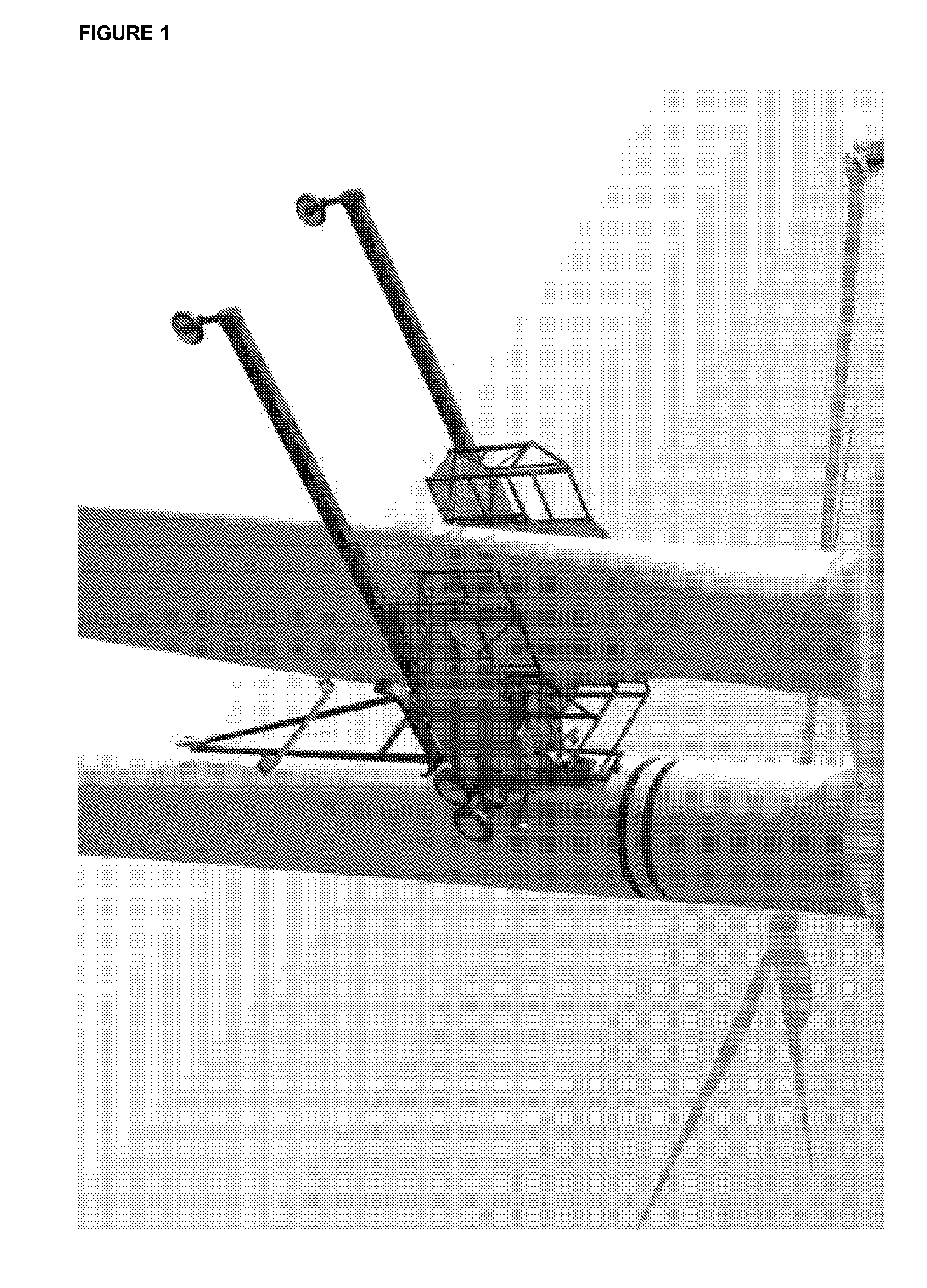
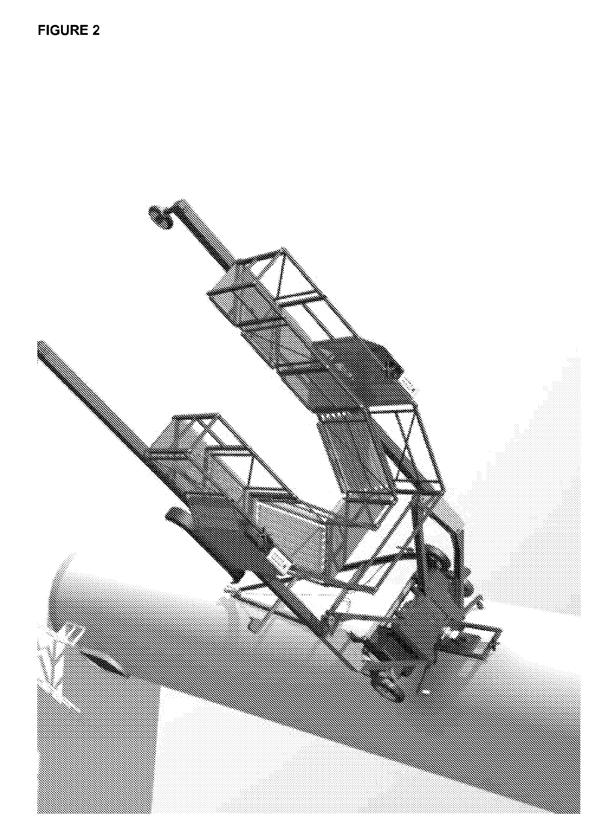
[0051]FIG. 2 provides a separate view of the maintenance platform. The maintenance platform is comprised of 5 sub-platforms swivably connected to each other by four joints to form a horse shoe shaped four-bar linkage.

[0052]One characteristic of the maintenance platform is that the workspace enclosed by maintenance platform can be modified by swiv...


PUM


Abstract

There is provided a suspendable maintenance platform for accessing a blade of a wind turbine. The platform includes arms for holding a maintenance unit, a frame onto which each arm is movably attached in a joint enabling planar movement, and means for supporting the frame in relation to the wind turbine tower. The maintenance unit is slidably attached to the arms that are configured for positioning the platform in relation to the blade, and wherein the frame is configured to be in close proximity to the turbine tower.

Description

TECHNICAL FIELD[0001]The invention relates to a secure maintenance platform for suspension on cables, in particular for maintaining wind turbine blades.BACKGROUND OF THE INVENTION[0002]In many countries wind turbines are deemed by law to be building structures, the engineering design, erection and operation of which are supervised by the building permit offices and by the locally competent building authorities.[0003]The competent authorities require above all that wind turbines, and especially their rotor blades and mechanical engineering components, be monitored at periodic intervals to maintain their operational safety. Irrespective of such requirements, regular maintenance and repair are essential for maximum availability of wind turbines.[0004]In the first years of wind power use, telescopic platforms or so-called aerial platforms, mounted on trucks, were used for inspecting, maintaining and repairing rotor blades.[0005]Owing to the rapid increase in the hub heights of wind turb...

Claims


Application Information

Patent Timeline
IPC IPC(8): F03D11/00E04G3/24E04G5/00E04G3/32
CPCF03D1/003F03D11/0016F05B2240/912Y02E10/722Y02E10/726Y02E10/728F05B2240/916F03D80/50F03D80/55Y02E10/72
Inventor LOTT, KENNETH SKOVBO
Owner LOTT KENNETH SKOVBO
Why Eureka
Try Eureka