
Movable wrench

a technology of moving wrenches and wrenches, which is applied in the field of moving wrenches, can solve the problems of elongating the lifetime of the wrench, and achieve the effects of prolonging the lifetime, preventing the deformation of the wrench, and prolonging the lifetim

Inactive Publication Date: 2011-02-03
NEW WAY TOOLS
View PDF7 Cites 4 Cited by
  • Summary
  • Abstract
  • Description
  • Claims
  • Application Information

AI Technical Summary

Benefits of technology

[0011]An objective of the invention is to solve the above-mentioned problems by providing a movable wrench. By changing the configuration of the operating end and the operating space, it can prevent dusts and impurities from falling in between. So the invention does not stuck because of this. It thus has a longer lifetime.
[0012]Another objective of the invention is to provide a movable wrench in which most of the operating element is disposed in an inner groove. This prevents the wrench from deforming due to collisions when it is put away inappropriately, thereby elongating its lifetime.
[0013]Yet another objective of the invention is to provide a movable wrench in which the bottom surface of the operating element urge against the bottom surfaces of the accommodating cavity and the inner groove. The operating element does not need to sustain a large pressure alone. This avoids the deformation problem.
[0014]A further objective of the invention is to provide a movable wrench in which the operating space is on the connecting part and in the vicinity of the holder. As the user rotates it, his palm would not incorrectly touch the operating end. This ensures work safety.
[0015]To achieve the above-mentioned objectives, the invention includes: a fixed jaw, a connecting part, a holder, a movable jaw, a screw bar, a first compressible spring, and an operating element. The fixed jaw and the movable jaw correspond to each other. The connecting part connects the fixed jaw, the movable jaw, and the holder. The screw bar is disposed at the connecting part. The operating element is pivotally disposed on the connecting part near the holder. The operating element and the screw bar have a locking relation. When the user's palm holds the holder, he can use his thumb to depress the operating element, thereby achieving locking and positioning effects.

Problems solved by technology

This prevents the wrench from deforming due to collisions when it is put away inappropriately, thereby elongating its lifetime.

Method used


Image

  • Movable wrench
  • Movable wrench
  • Movable wrench

Examples


Embodiment Construction

[0026]The present invention will be apparent from the following detailed description, which proceeds with reference to the accompanying drawings, wherein the same references relate to the same elements.

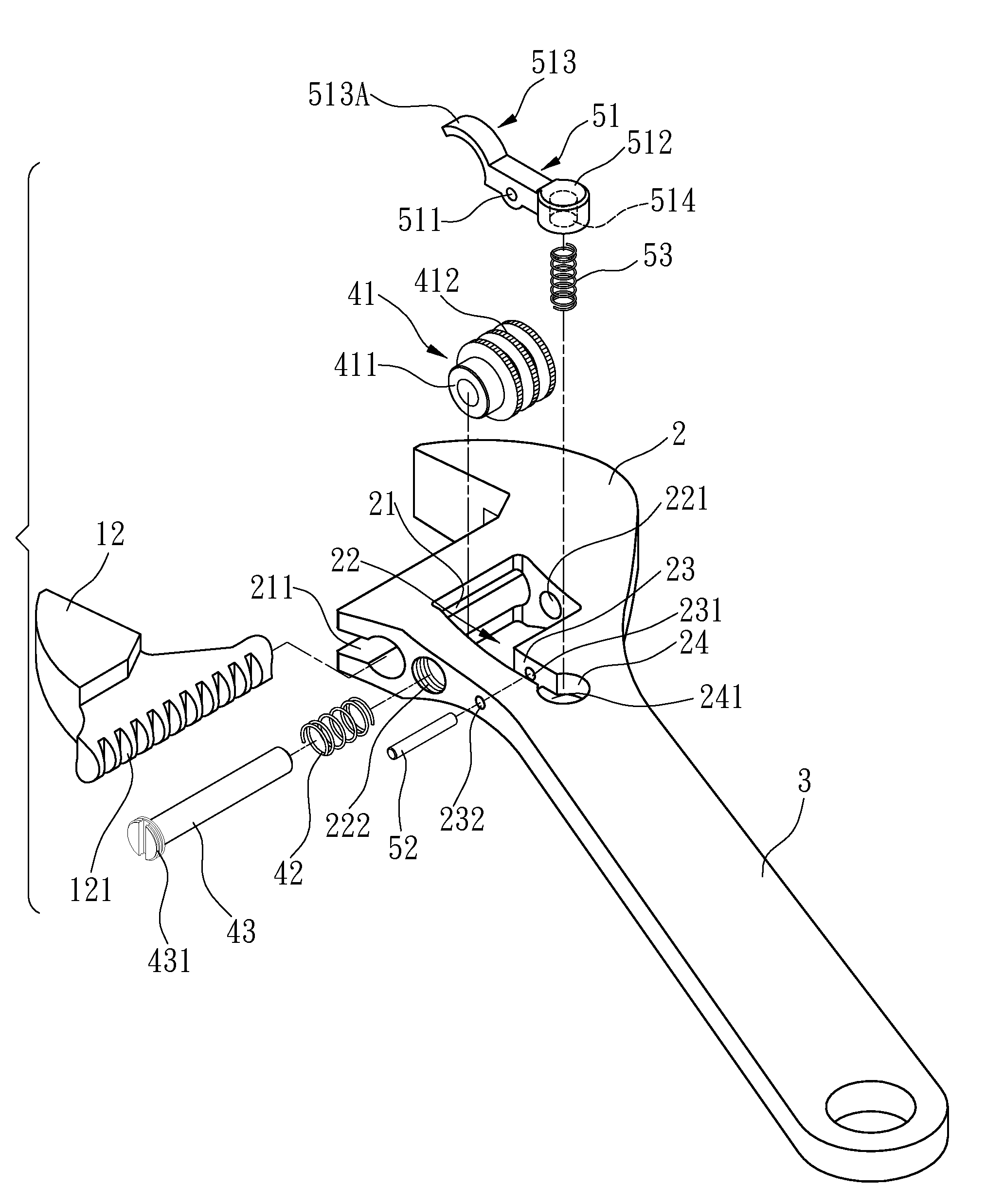
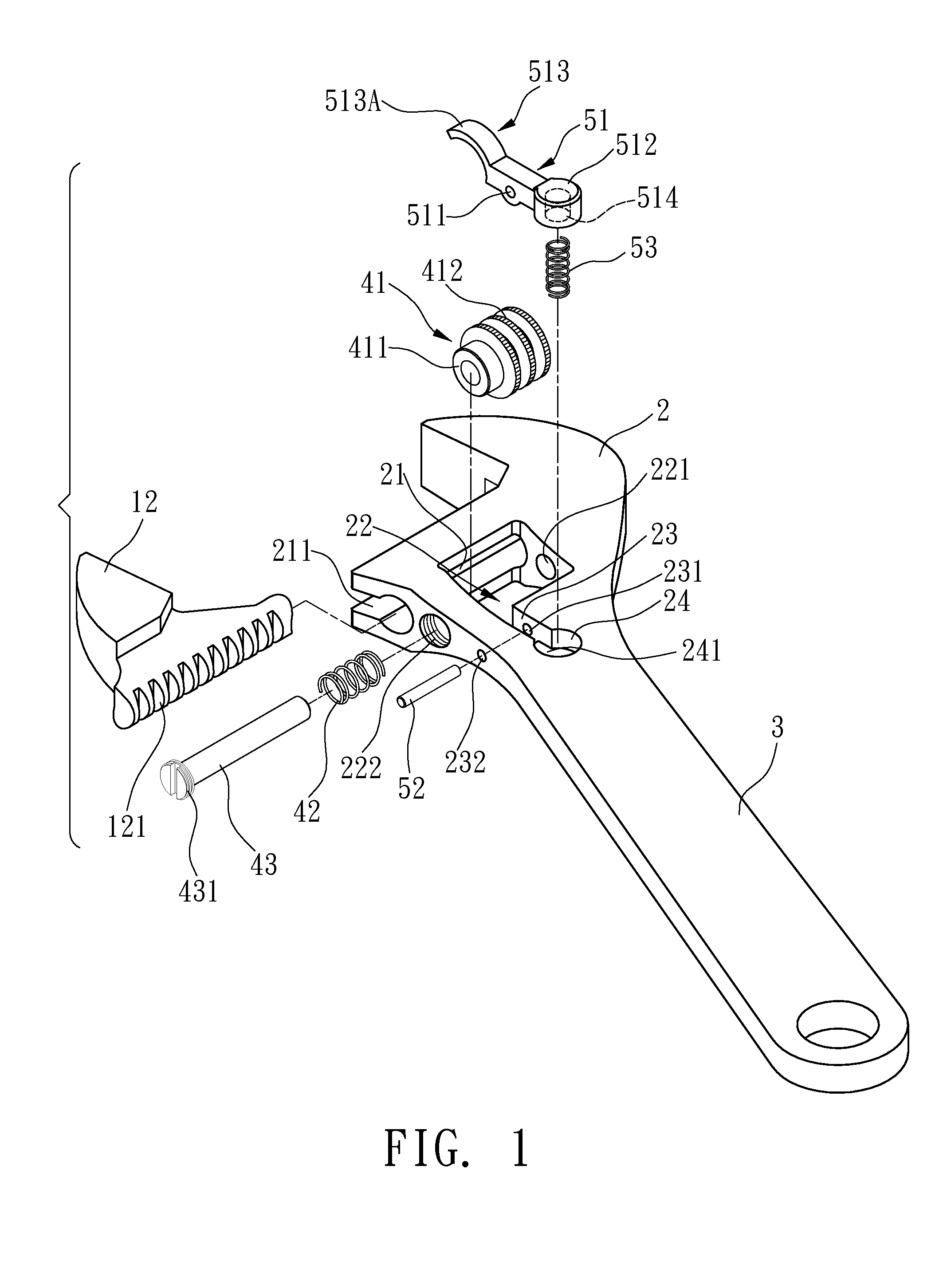
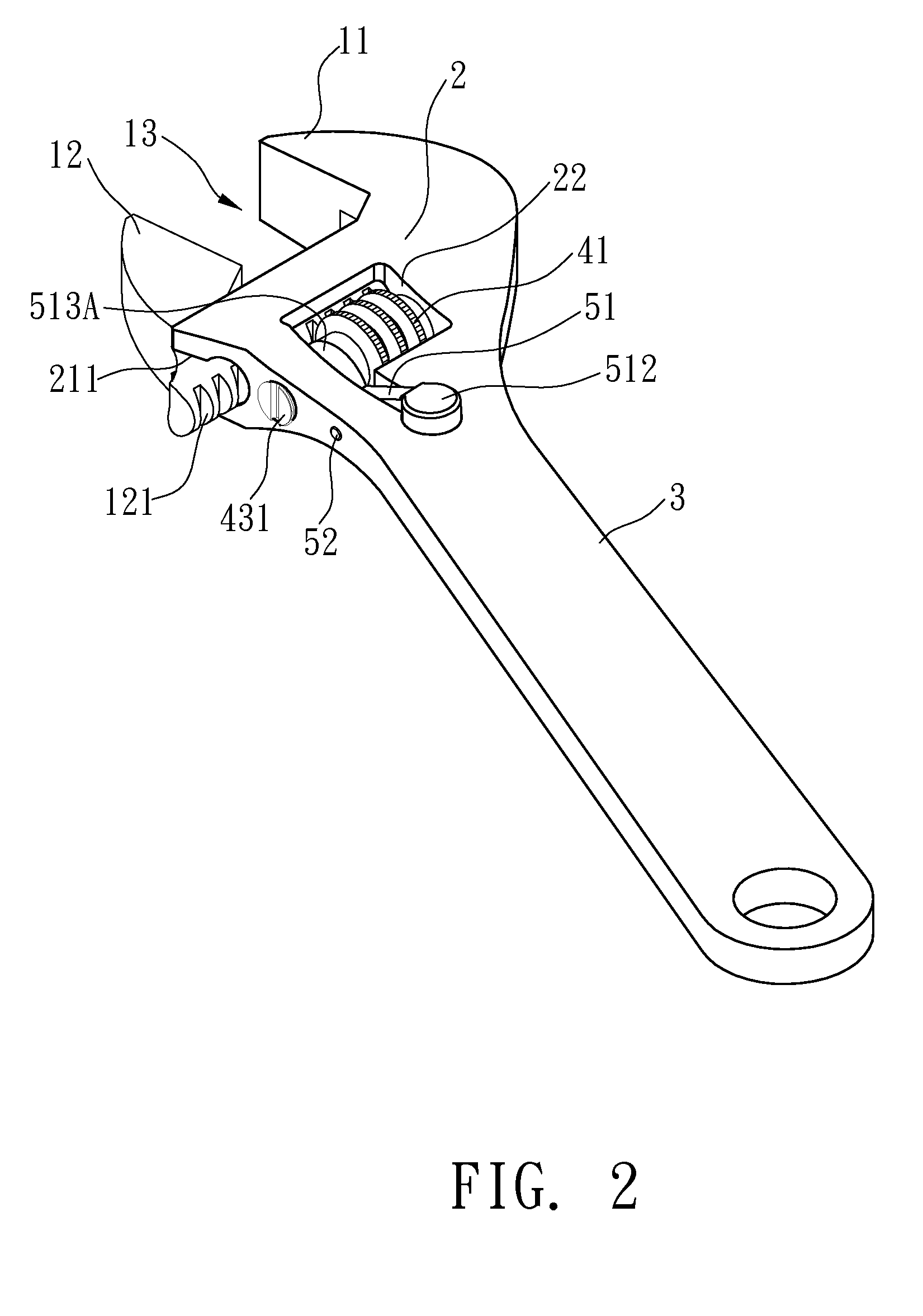
[0027]Please refer to FIG. 1 to 3. The following embodiment is a movable wrench, which includes a fixed jaw 11, a movable jaw 12, a screw bar 41, a first compressible spring 42, a shaft 43, an operating element 51, a pin 52, and a second compressible spring 53.

[0028]One side of the fixed jaw 11 is extended with a connecting part 2, which in turn is extended with a holder 3 away from the fixed jaw 11. One side of the connecting part 2 under the fixed jaw 11 is formed with a sliding track 21. In this embodiment, the sliding track 21 is formed with rectangular and round cross sections. The bottom surface of the connecting part2 below the sliding track 21 is formed with an insertion opening 211.

[0029]The inner side surface of the sliding track 21 that faces the holder 3 is formed with a r...


PUM


Abstract

A movable wrench including a screw bar, and an operating element. The bottom surface of the screw bar is urged by a first compressible spring. The hook part of the operating element urges against the bottom surface of the screw bar. As the user depresses the operating end of the operating element, the hook part escape from the bottom surface. The first compressible spring is depressed downward. After the reverse rotation and positioning, the first compressible spring urges against the screw bar again. The operating end is released so that the hook part urges against the bottom surface again.

Description

BACKGROUND OF THE INVENTION[0001]1. Field of Invention[0002]The invention relates to a movable wrench and, in particular, to a wrench that is convenient in performing reciprocal rotations.[0003]2. Related Art[0004]Traditionally, one needs to adjust a roller before using a movable wrench so that the holding opening between its fixed jaw and movable jaw matches with the size of a screw nut in order to rotate it.[0005]However, when space is limited, it is difficult to hold the wrench and rotate the nut continuously. Instead, one has to loosen the roller to enlarge the holding opening and snap another two opposite surfaces of the nut. This is rather inconvenient.[0006]To solve the above-mentioned problem, U.S. Pat. No. 3,022,689 discloses a wrench, as shown in FIG. 7. It includes a holder 66 for the user to hold. One end of the holder 66 has a fixed jaw 68. One side of the fixed jaw 68 is provided with a movable jaw 62 that matches with a roller 61 and drives the movable jaw 62. The rol...

Claims


Application Information

Patent Timeline
Patent Type & Authority Applications(United States)
IPC IPC(8): B25B13/16
CPCB25B13/46B25B13/14
Inventor HUANG, PING WEN
Owner NEW WAY TOOLS
Learn More