
Electronic information device and method of controlling the same

a technology of electronic information and control method, applied in the direction of electrical equipment, substation equipment, eavesdropping prevention circuit, etc., can solve problems such as privacy infringement, and achieve the effects of high security, increased security, and reliably recognition

Inactive Publication Date: 2011-01-27
KYOCERA CORP
View PDF4 Cites 6 Cited by
  • Summary
  • Abstract
  • Description
  • Claims
  • Application Information

AI Technical Summary

Benefits of technology

The present invention provides an electronic information device with a function restriction process that restricts part of functions of the device. To increase security and convenience, a personal identification code is generated and released when starting the function restriction process. The personal identification code can be randomly selected, and it is displayed and pronounced for the user's convenience. The generated personal identification code can be transmitted in an e-mail to the user, allowing them to retrieve their personal identification code even if they forget it. Overall, the invention provides an electronic information device with high security and convenience.

Problems solved by technology

If a third party makes unauthorized use of this large quantity of personal data, there is an infringement of privacy.

Method used


Image

  • Electronic information device and method of controlling the same
  • Electronic information device and method of controlling the same
  • Electronic information device and method of controlling the same

Examples


embodiment 1

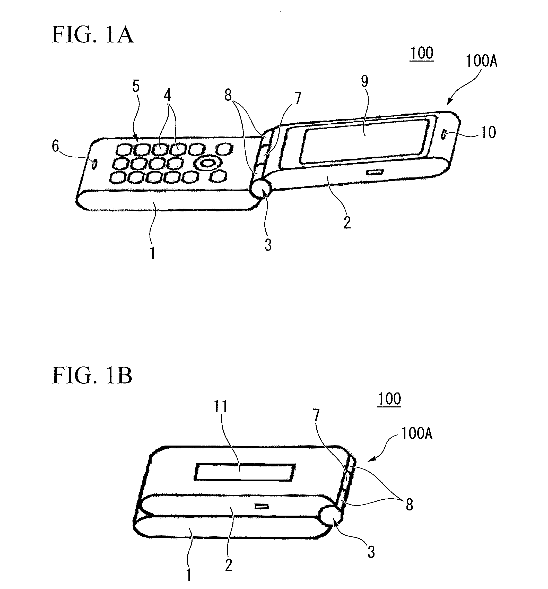
[0061]FIGS. 1A and 1B are explanatory views of the total configuration of a mobile telephone unit in accordance with the first preferred embodiment of the present invention.

[0062]FIG. 1A is a perspective view of an in-use state (open state) of a mobile telephone unit, and FIG. 1B is a perspective view of a stored state (closed state) of the mobile telephone unit.

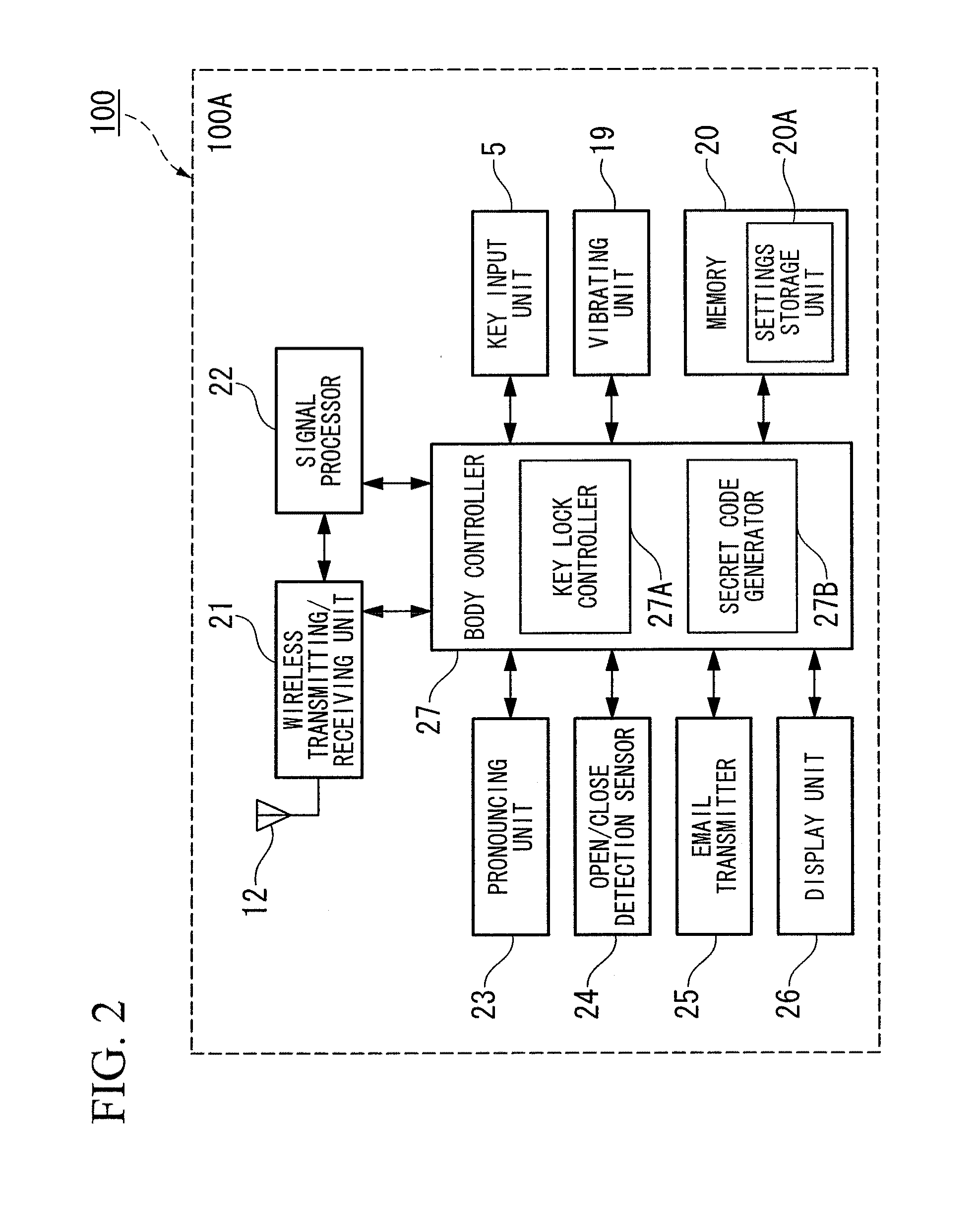
[0063]A mobile telephone unit 100 (electronic information device) includes a mobile telephone unit body 100A (electronic information device body) formed by connecting a first casing 1 (body member), a second casing 2 (body member) via a hinge 3. The first casing 1 includes a key input unit 5 (manipulation input unit) in one face. The second casing 2 includes a screen display unit 9 in one face. The mobile telephone unit 100 (electronic information device) is folded and stored in a state where the screen display unit 9 and the key input unit 5 (manipulation input unit) are opposite each other with the first casing 1 and the s...

second embodiment

[0094]FIG. 4 is an explanatory perspective view illustrating an overall configuration of a mobile telephone unit in accordance with the second preferred embodiment of the present invention. FIG. 5 is a block diagram illustrating a schematic configuration of a mobile telephone unit in accordance with the second preferred embodiment of the present invention.

[0095]A mobile telephone unit 200 (electronic information device) in accordance with the second preferred embodiment of the present invention is a straight-type mobile telephone which does not have a folding structure. A casing 201 of the mobile telephone unit 200 includes a key input unit 5 and a screen display unit 9 within the same face. The casing 201 also includes a receiver speaker 10 and a microphone 6 for transmitting, at the top end and the bottom end of the face where the key input unit 5 and the screen display unit 9 are disposed.

[0096]The key input unit 5 in accordance with the second preferred embodiment of the present...


PUM


Abstract

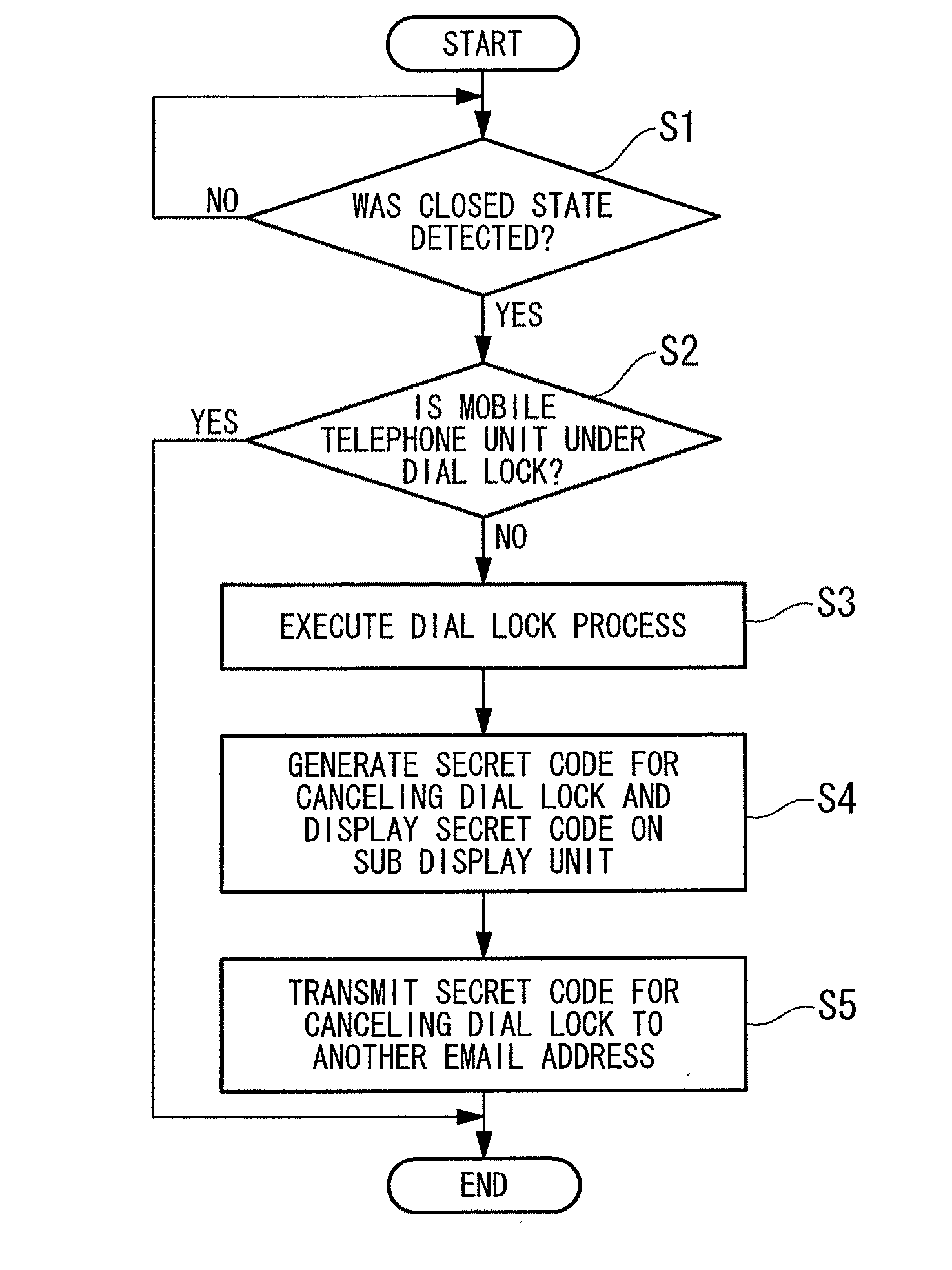
Provided is a mobile telephone that performs a dial lock process for regulating some functions. The mobile telephone may include a personal identification code generating unit that generates a personal identification code for releasing the dial lock process when starting the dial lock process, and an outputting unit that outputs the personal identification code that is generated.

Description

TECHNICAL FIELD[0001]The present invention relates to an electronic information device and method of controlling the same.[0002]Priority is claimed on Japanese Patent Application No. 2007-335572, filed Dec. 27, 2007, the content of which is incorporated herein by reference.BACKGROUND ART[0003]Recently, there is rapid progress in increasing the performance of electronic information devices such as mobile telephones, which have more advanced functions such as large-capacity telephone number storage and transmission / reception of e-mail. One consequence of these functional advancements is that a large quantity of personal data, including private information such as names, telephone numbers, and e-mail addresses of individuals, is stored in the memory of the mobile telephone. If a third party makes unauthorized use of this large quantity of personal data, there is an infringement of privacy. Therefore, means to prevent unauthorized use by a third party are required. As a means of prevent...

Claims


Application Information

Patent Timeline
Patent Type & Authority Applications(United States)
IPC IPC(8): H04M1/66
CPCH04M1/72552H04M1/673H04M1/72436
Inventor NAKAMURA, TOSHIAKI
Owner KYOCERA CORP
Learn More