Printing apparatus

a printing machine and printing plate technology, applied in printing, typewriters, instruments, etc., can solve the problems of waste, limited control of the outer diameter and feed speed of the platen roller, and the inability to accurately manage the outer diameter and feed speed in the platen roller, etc., to achieve smooth paper conveying

Inactive Publication Date: 2011-01-27
TOSHIBA TEC KK
View PDF18 Cites 0 Cited by
  • Summary
  • Abstract
  • Description
  • Claims
  • Application Information

AI Technical Summary

Benefits of technology

[0017]An object of the invention is to smoothly convey the paper without strictly managing the outer diameter of the platen roller while the proper tension is applied to the thermal recording paper, when the two platen rollers are driven by the same drive motor.
[0019]Another object of the invention is to decrease breakage of the device and a load during the paper conveyance to enhance the life and reliability of the device by decreasing unnecessary contact and slide as much as possible.

Problems solved by technology

In the conventional double-side printing thermal printer, when the first platen roller differs slightly from the second platen roller in a feed speed, looseness of the thermal recording paper is generated between the pair of platen rollers, or tension is excessively applied to the thermal recording paper, which possibly results in a problem with print quality.
However, because the platen roller is made of a rubber material having elasticity, there is a limitation to the accurate management of the outer diameter and feed speed in the platen roller.
Because the double-side printing is simultaneously started while the paper is entrained between the first printing unit and the second printing unit, the printing start positions are displaced between one surface and the other surface of the paper, which generates waste.
Therefore, when the paper is reversely conveyed such that the printing start positions are aligned with each other, the reversal feed amount of the paper by the platen roller of the first printing unit becomes larger than that of the platen roller of the second printing unit, and the looseness is generated in the paper, which causes a conveyance trouble.
Furthermore, because the number of printing units is increased to increase resistance against the paper conveyance, necessary power is increased, which results in a problem that breakage or wear of each component easily occurs.

Method used


Image

  • Printing apparatus
  • Printing apparatus
  • Printing apparatus

Examples


first embodiment

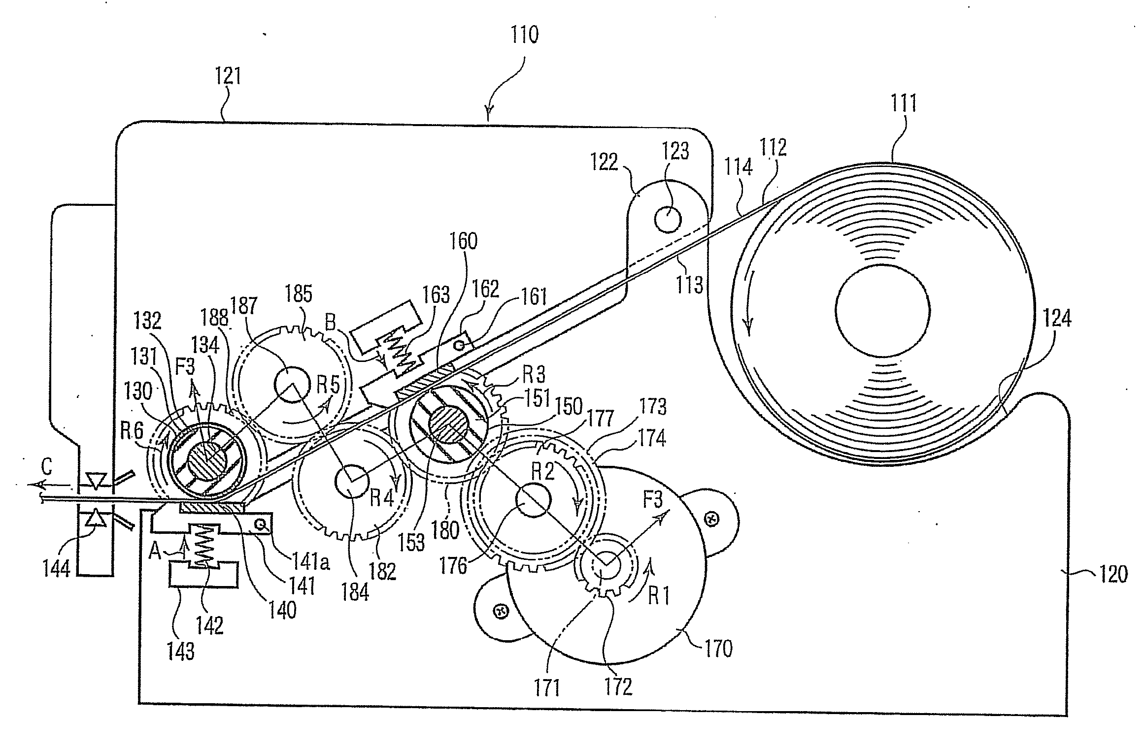
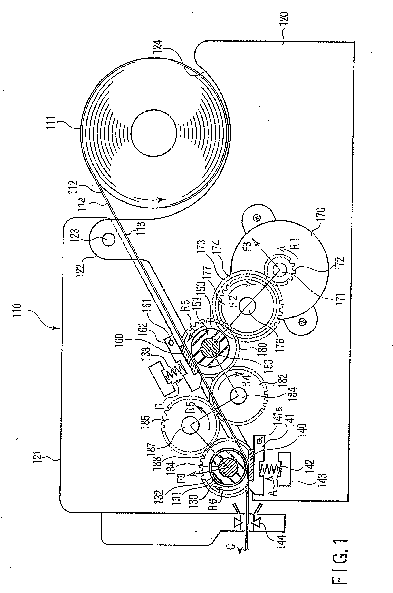
[0055]FIG. 1 schematically shows an inside of a thermal printer 110 according to a first embodiment of the invention. The thermal printer 110 can carry out printing on both surfaces of thermal recording paper 111. For example, the thermal printer 110 can be used in a cash register of a store.

[0056]As shown in FIG. 2, the thermal recording paper 111 includes a base paper 112 and heat-sensitive layers 113 and 114 which are formed on both the surfaces of the base paper 112. The first heat-sensitive layer 113 is formed on one side (for example, surface) of the base paper 112, and the second heat-sensitive layer 114 is formed on the other side (for example, backside) of the base paper 112. Each of the heat-sensitive layers 113 and 114 is made of a material which develops a desired color such as black and red when heated to a predetermined temperature or more. As shown in FIG. 1, the thermal recording paper 111 is wound in a roll shape such that the first heat-sensitive layer 113 faces th...

second embodiment

[0087]A thermal printer 190 according to a second embodiment of the invention will be described below.

[0088]The second embodiment differs from the first embodiment only in the first and second platen rollers 130 and 150 and first and second biasing means 191 and 192. Thus, the same components are designated by the same numerals and the description thereof is omitted.

[0089]In the second embodiment, a first platen roller 130a and a second platen roller 150a are formed by roller bodies 131a and 151a made of NBR respectively. The first platen roller 130a is slightly larger than the second platen roller 150a in the diameter.

[0090]The first biasing means 191 is smaller than the second biasing means 192 in a spring constant. For example, a wire diameter in the spring of the first biasing means 191 is smaller than that of the second biasing means 192. Therefore, the force with which the first thermal head 140 is pressed against the first platen roller 130a by the first biasing means 191 bec...

third embodiment

[0096]FIG. 6 schematically shows an inside of a thermal printer 210. The thermal printer 210 can carry out printing on both surfaces of thermal recording paper 211. For example, the thermal printer 210 can be used in a cash register of a store.

[0097]As shown in FIG. 7, the thermal recording paper 211 includes a base paper 212 and heat-sensitive layers 213 and 214 which are formed on both the surfaces of the base paper 212. The first heat-sensitive layer 213 is formed on one side (for example, surface) of the base paper 212, and the second heat-sensitive layer 214 is formed on the other side (for example, backside) of the base paper 212. Each of the heat-sensitive layers 213 and 214 is made of a material which develops a desired color such as black and red when heated to a predetermined temperature or more. As shown in FIG. 6, the thermal recording paper 211 is wound in the roll shape such that the first heat-sensitive layer 213 faces the inside.

[0098]The thermal printer 210 includes...


PUM


Abstract

A thermal printer includes a first thermal head, a first platen roller, first biasing means, a second thermal head, a second platen roller, and second biasing means. The first thermal head, the first platen roller, the first biasing means are in contact with a heat-sensitive layer of thermal recording paper. The second thermal head, the second platen roller, and the second biasing means are in contact with a heat-sensitive layer of the thermal recording paper. The second thermal head is arranged on the upstream side of the first thermal head in a paper feed direction. A paper feed speed of the first platen roller to the thermal recording paper is larger than a paper feed speed of the second platen roller. The first platen roller is in contact with the thermal recording paper while being more slippery compared with the second platen roller.

Description

CROSS-REFERENCE TO RELATED APPLICATIONS[0001]This is a Division of application Ser. No. 11 / 681,916 filed Mar. 5, 2007, the entire contents of which are incorporated herein by reference.[0002]This application is based upon and claims the benefit of priority from prior Japanese Patent Applications No. 2006-178941, filed Jun. 29, 2006; No. 2006-178942, filed Jun. 29, 2006; No. 2006-178943, filed Jun. 29, 2006; No. 2006-178949, filed Jun. 29, 2006; No. 2006-178950, filed Jun. 29, 2006; No. 2006-178952, filed Jun. 29, 2006; No. 2006-178954, filed Jun. 29, 2006; and No. 2006-178955, filed Jun. 29, 2006, the entire contents of all of which are incorporated herein by reference.BACKGROUND OF THE INVENTION[0003]1. Field of the Invention[0004]The present invention relates to a printing apparatus, and particularly to a technology in which paper can smoothly be conveyed and a technology in which a long life and high reliability are obtained in the printing apparatus.[0005]2. Description of the R...

Claims


Application Information

Patent Timeline
Patent Type & Authority Applications(United States)
IPC IPC(8): B41J2/325
CPCB41J2/32B41J11/44B41J3/60
Inventor SEKINO, TOSHIHARUEOKA, KENJINIHASHI, KIYOTAKAHIYOSHI, TAKESHISANADA, TSUYOSHISUZUKI, AKIRA
Owner TOSHIBA TEC KK
Why Eureka
Try Eureka