Passenger comfort strap, used on motorized and or non-motorized devices. Biker buddy comfort strap

a technology for comfort straps and motorized devices, which is applied in the direction of cycle safety equipment, cycle containers, cycle equipment, etc., can solve the problems of difficult for passengers to hold onto the driver of the device, and achieve the effect of convenient and quick removal of the strap assembly and more comfortable position

Inactive Publication Date: 2011-01-27
GIZZARELLI JR JOHN JAMES
View PDF39 Cites 2 Cited by
  • Summary
  • Abstract
  • Description
  • Claims
  • Application Information

AI Technical Summary

Benefits of technology

[0004]The following invention relates to devices that are not needed to be attached to any motorized or non-motorized device. More particularly this invention relates to a device which is attached to only the driver by means of two steel o rings, which must be slid through drivers belt and be positioned in between the two front belt loops, with said strap loops positioned rearwardly. The passenger must grasp outside perimeter of both end loops, while riding on the back of a motorized or motorized device. Said strap will provide support for the hands of a rear passenger and a more comfortable position for the driver and passenger while riding on a motorized or non-motorized device
[0005]With said invention the biker buddy passenger comfort strap provides the passenger and driver a more comfortable position on long and short rides. Said assembly provides a position for said driver and passenger to have a less intimate contact if desired.
[0006]With this invention said strap assembly provides a more comfortable and enjoyable position for said driver and passenger riding on a motorized or non motorized device. Strap assembly provides two looped handle areas for passenger to grasp outside perimeter of sed loops located on either side of said strap assembly. The strap assembly consist of a first loop, center span, and then a second loop located on the opposite side of the first loop. The strap is made with a steel cable, and or similiar man made or natural material. Ferrules are then used to create both loops and ferrules are used in center span to attach both ends of the continous steel cable and or similiar man made or natural material. When the said assembly is in the correct form similiar to the number eight. The cable is then encased and finished in a variety of finishes consisting of but not limited to a flexible rubber, leather braid, split suede hides, variety of ropes, and other similiar materials to provide an attractive and comfortable finished product. Two steel o-rings are provided with said strap which slide through drivers belt and are to be positioned behind both front belt loops of drivers pants. Strap assembly will then be slid through each steel o-ring and be positioned where as center span is located in between drivers front belt loops and each loop is located on opposite sides of drivers waist area facing rearwardly. Steel o-rings enable the driver to easily and quickly remove the strap assembly when not being used. This invention provides a more comfortable position for said driver and passenger when riding on a motorized or non motorized device.

Problems solved by technology

This means of holding onto said driver is usually inadequate and creates a posture for the driver and passenger which can be very intimate and awkward for both, Also uncomfortable on long and or short rides for both the driver and passenger.
In addition in some circumstances the operator may have a large stomach and or waist area which could make it difficult for the passenger to hold onto the driver of said device.

Method used


Image

  • Passenger comfort strap, used on motorized and or non-motorized devices. Biker buddy comfort strap
  • Passenger comfort strap, used on motorized and or non-motorized devices. Biker buddy comfort strap
  • Passenger comfort strap, used on motorized and or non-motorized devices. Biker buddy comfort strap

Examples


Embodiment Construction

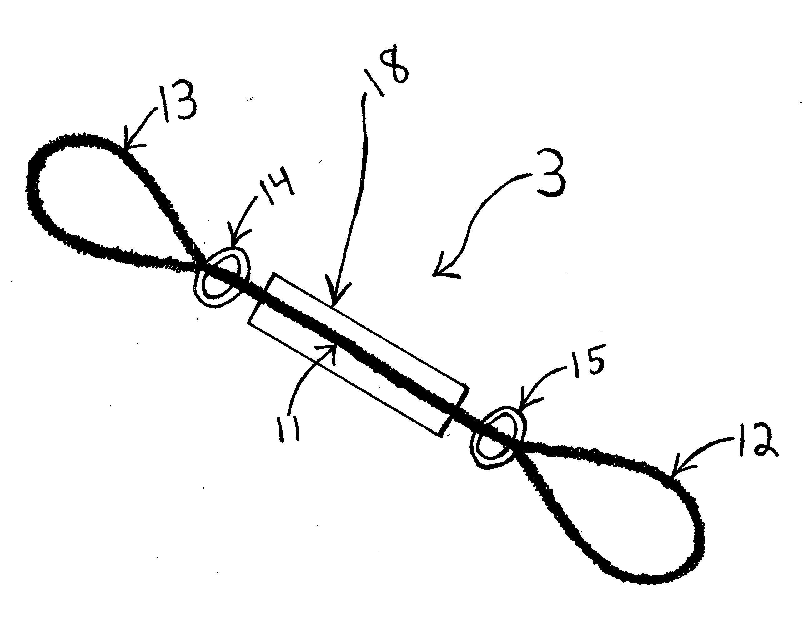
[0011]FIG. 1. number 3. Is a perspective view of a preferred embodiment of the invention which illustrates the internal steel cable or similiar man made or natural continous material in a specific configuration as shown with numbers 7,8,9,10. The material can range in a diameter from 1 / 16 of an inch to ⅜ of an inch. FIG. 1. numbers 7, 8, illustrates a loop at each end of the center span of the said assembly. FIG. 1. numbers 9,10, illustrates the center span of the said assembly. FIG. 1. numbers 4, 5, 6, illustrates where the said assembly is secured with a ferrule by means of using a swagging tool to ensure proper configuration. FIG. 1 numbers 4,5,6, shows where ferrules will be used in accordance with said assembly diameter. FIG. 1. number 3 shows continous length of material set in a position to maintain a specific shape and length. FIG. 1. number 5 illustrates where a ferrule is positioned at the center span which will be crimped using a swagging tool to ensure both ends of the c...


PUM


Abstract

A strap assembly that is not attached to a motorcycle, or any other gas or diesel powered device, or non-powered device for example a horse, bull , etc. The strap assembly attaches to the driver by means of two steel o-rings which are slid through the drivers belt and must be positioned behind the drivers front belt loops. The strap then must be slid through each steel o-ring which are located behind each front belt loop of drivers pants and be positioned so center portion of strap is in between both front belt loops. The end loops must be located on either side of drivers waist area extending rearwardly, allowing the passenger to grasp outside perimeter of each loop. Entire strap is made from flexible components to ensure a comfortable position for the driver and passenger.

Description

CROSS REFERENCE RELATED APPLICATION[0001]This application is based on the provisional application No. 61271747 filed on Jul. 24, 2009.[0002]Most motorized and non-motorized devices have an elongated seat and are able to accommodate two riders, a driver and a rear passenger. The driver or operator maintains proper balance and a comfortable position by means of holding onto the said steering assembly. The passenger of said device in most circumstances must hold onto said drivers waist or stomach area. This means of holding onto said driver is usually inadequate and creates a posture for the driver and passenger which can be very intimate and awkward for both, Also uncomfortable on long and or short rides for both the driver and passenger. In addition the passenger must have intimate contact with said operator of said device. In addition in some circumstances the operator may have a large stomach and or waist area which could make it difficult for the passenger to hold onto the driver ...

Claims


Application Information

Patent Timeline
Patent Type & Authority Applications(United States)
IPC IPC(8): B62J27/00B62J99/00
CPCB62J27/00
Inventor GIZZARELLI, JR., JOHN JAMES
Owner GIZZARELLI JR JOHN JAMES
Why Eureka
Try Eureka