
Small smart weapon and weapon system employing the same

a smart weapon and small technology, applied in the field of weapons systems, can solve the problems of difficult qualification, complicated qualification, and high cost of qualification tests, and achieve the effect of improving the quality of qualification and reducing the cost of developmen

Inactive Publication Date: 2011-01-27
LONE STAR IP HLDG LP
View PDF107 Cites 24 Cited by
  • Summary
  • Abstract
  • Description
  • Claims
  • Application Information

AI Technical Summary

Benefits of technology

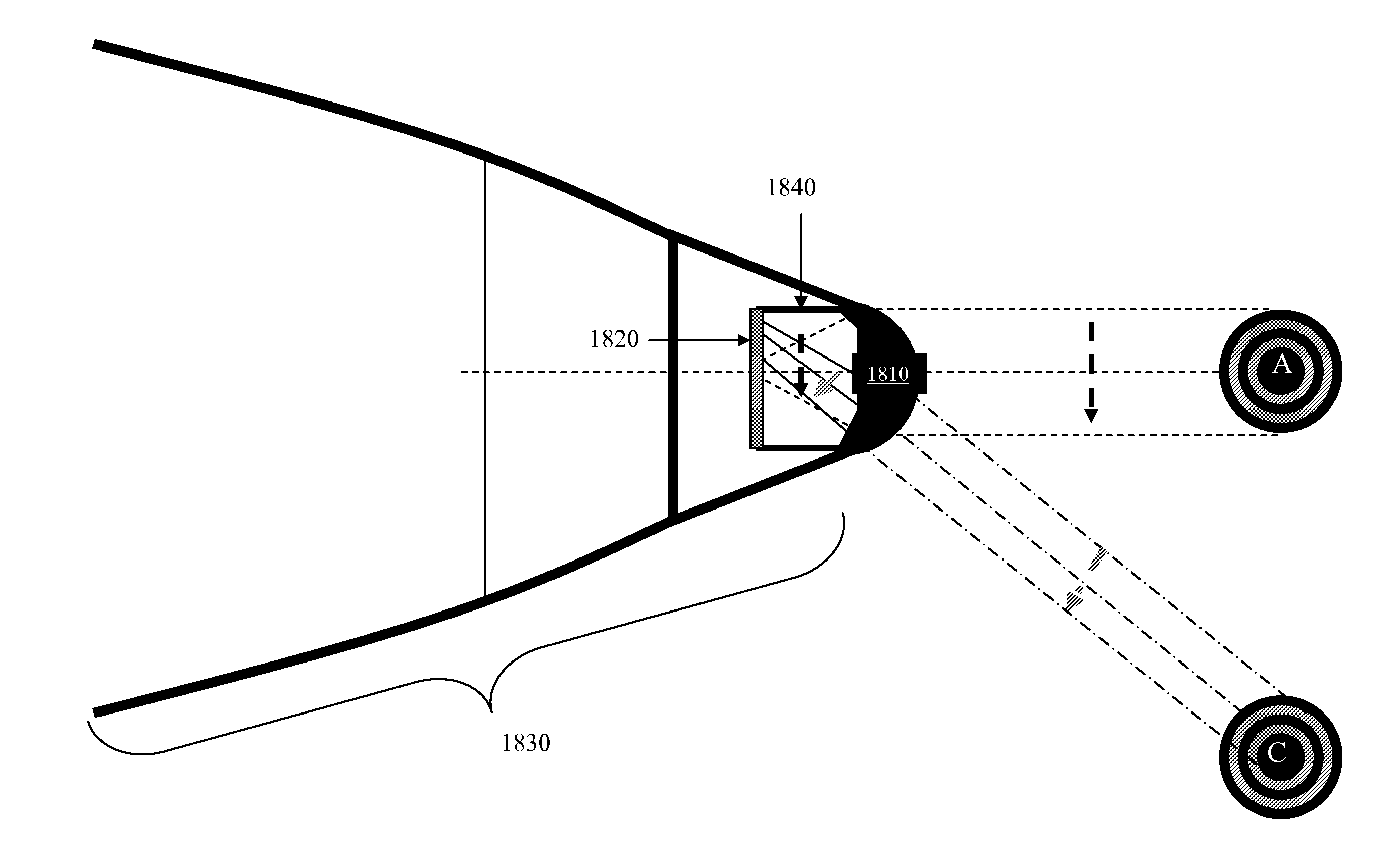
[0013]These and other problems are generally solved or circumvented, and technical advantages are generally achieved, by advantageous embodiments of the present invention, which includes a weapon and weapon system, and methods of manufacturing and operating the same. In one embodiment, the weapon includes a warhead including destructive elements and a guidance section with a seeker configured to guide the weapon to a target. The seeker includes a detector configured to receive a distorted signal impinging on an objective lens from the target, memory configured to store target criteria and a correction map, and a processor configured to provide a correction signal based on the distorted signal, the target criteria and the correction map to guide the weapon to the target.

Problems solved by technology

In some cases, these qualification tests can cost more to perform than the costs of the development of the weapon system.
Such qualifications can be very complex.
As weapons have become more complex, this has proven to be difficult.
As a result, the delay in operational deployment of new weapons has been measured in years, often due solely to the problem of aircraft software integration.
Another general issue to consider is that low cost weapons are best designed with modularity in mind.
Such damage can take many forms, including direct damage from an exploding weapon, or indirect damage.
Indirect damage can be caused by a “dud” weapon going off hours or weeks after an attack, or if an enemy uses the weapon as an improvised explosive device.
The damage may be inflicted on civilians or on friendly forces.
In recent United States engagements, insurgent forces fighting from urban positions have been difficult to attack due to such considerations.

Method used


Image

  • Small smart weapon and weapon system employing the same
  • Small smart weapon and weapon system employing the same
  • Small smart weapon and weapon system employing the same

Examples


Embodiment Construction

[0039]The making and using of the presently preferred embodiments are discussed in detail below. It should be appreciated, however, that the present invention provides many applicable inventive concepts that can be embodied in a wide variety of specific contexts. The specific embodiments discussed are merely illustrative of specific ways to make and use the invention, and do not limit the scope of the invention.

[0040]It should be understood that the military utility of the weapon can only be fully estimated in the context of a so-called system of systems, which includes a guidance section or system, the delivery vehicle or launch platform, and other things, in addition to the weapon per se. In this sense, a weapon system is disclosed herein, even when we are describing a weapon per se. One example is seen in the discussion of the GBU-12, wherein design choices within the weapon were reflected in the design and operation of many aircraft that followed the introduction of the GBU-12. ...


PUM


Abstract

A weapon and weapon system, and methods of manufacturing and operating the same. In one embodiment, the weapon includes a warhead including destructive elements and a guidance section with a seeker configured to guide the weapon to a target. The seeker includes a detector configured to receive a distorted signal impinging on an objective lens from the target, memory configured to store target criteria and a correction map, and a processor configured to provide a correction signal based on the distorted signal, the target criteria and the correction map to guide the weapon to the target.

Description

[0001]This application is a continuation-in-part of U.S. patent application Ser. No. 11 / 706,489 entitled “Small Smart Weapon and Weapon System Employing the Same,” filed Feb. 15, 2007,which is a continuation-in-part of U.S. patent application Ser. No. 11 / 541,207 entitled “Small Smart Weapon and Weapon System Employing the Same,” filed Sep. 29, 2006, now U.S. Pat. No. 7,690,304, and also claims the benefit of U.S. Provisional Application No. 61 / 231,141 entitled “Novel Body Fixed Seekers and Variable Output Explosive Devices,” filed Aug. 4, 2009, which applications are incorporated herein by reference.TECHNICAL FIELD[0002]The present invention is directed, in general, to weapon systems and, more specifically, to a weapon and weapon system, and methods of manufacturing and operating the same.BACKGROUND[0003]Present rules of engagement demand that precision guided weapons and weapon systems are necessary. According to well-documented reports, precision guided weapons have made up about ...

Claims


Application Information

Patent Timeline
Patent Type & Authority Applications(United States)
IPC IPC(8): G05D1/12
CPCF42B10/64F42B12/04F42B12/362F42B12/44F42B25/00F41G7/2246F42C15/20F41G7/226F41G7/2293F41G7/001F42C15/005
Inventor ROEMERMAN, STEVEN D.
Owner LONE STAR IP HLDG LP
Learn More