
Resource allocation in virtual routers

a virtual router and resource allocation technology, applied in the field of network data routing, can solve the problems of a number of ports and line cards, and can be relatively expensive components, and achieve the effect of reducing the cost of line cards and reducing the cost of network traffi

Inactive Publication Date: 2011-01-20
VERIZON PATENT & LICENSING INC
View PDF11 Cites 207 Cited by
  • Summary
  • Abstract
  • Description
  • Claims
  • Application Information

AI Technical Summary

Problems solved by technology

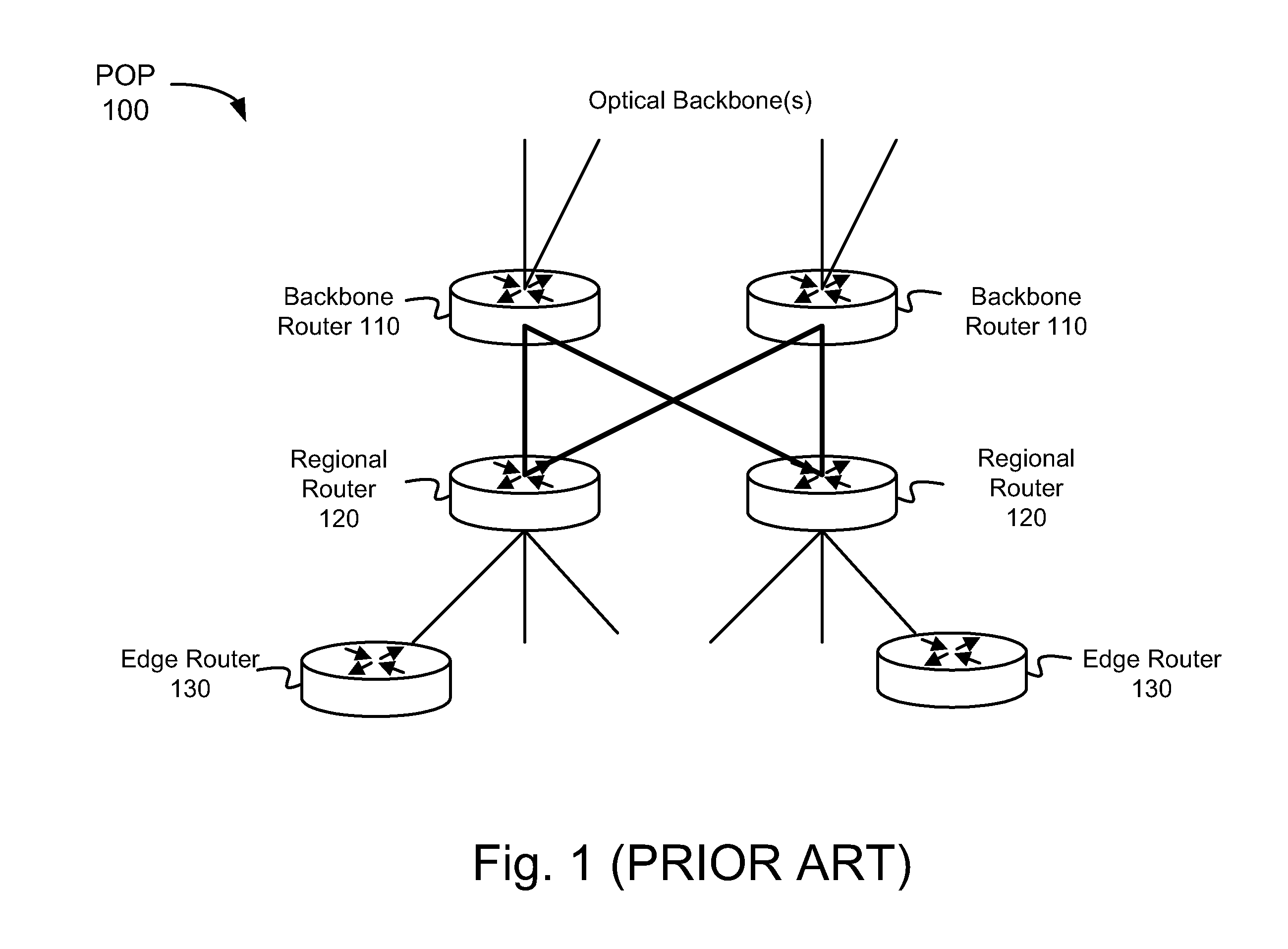
One disadvantage in the configuration of POP 100 is that the routers of POP 100 use a number of ports to communicate with one another.
Line cards, however, can be relatively expensive components.

Method used


Image

  • Resource allocation in virtual routers
  • Resource allocation in virtual routers
  • Resource allocation in virtual routers

Examples


Embodiment Construction

[0022]The following detailed description of the invention refers to the accompanying drawings. The same reference numbers may be used in different drawings to identify the same or similar elements. Also, the following detailed description does not limit the invention. Instead, the scope of the invention is defined by the appended claims and equivalents.

[0023]A router system, as described herein, includes a number of logically separated “virtual” routers that may perform the functions of traditional backbone routers, regional routers, and / or edge routers. The virtual routers of a single physical router may appear to the outside world as a number of traditional physical routers. The single physical router, in implementing the virtual routers, shares physical and logical resources that would traditionally be independently implemented by each of the virtual routers. The manner in which the physical and logical resources are shared may be a user programmable feature of the router.

EXEMPLA...


PUM


Abstract

A router system implements a plurality of virtual routers. Various combinations of resources may be shared by the router system when implementing the virtual routers. In one embodiment, the particular combination of resources to share when implementing the virtual router is user programmable.

Description

[0001]This application is a continuation of U.S. patent application Ser. No. 10 / 084,917, filed Mar. 1, 2002, which is incorporated herein by reference.BACKGROUND OF THE INVENTION[0002]A. Field of the Invention[0003]The present invention relates generally to network data routing and, more particularly, to high performance network routing systems.[0004]B. Description of Related Art[0005]Routers are devices that direct traffic flow through networks. In particular, routers receive data packets, determine the next network point to which the packets should be forwarded, and then transmit the packets to the determined next network point.[0006]In general, routers can be classified into a number of categories based on their traffic handling capacity or logical function. Backbone routers, for example, are high-performance routers that are typically implemented at the end-points of high-capacity network links. In the context of the Internet, for example, backbone routers may be implemented at ...

Claims


Application Information

Patent Timeline
Patent Type & Authority Applications(United States)
IPC IPC(8): G06F15/173H04L12/56
CPCH04L45/586H04L45/00H04L45/80
Inventor WANG, YANG
Owner VERIZON PATENT & LICENSING INC
Learn More