
Piezoelectric fan device and air-cooling apparatus using the piezoelectric fan device

a piezoelectric fan and fan device technology, applied in the direction of positive displacement liquid engines, piston pumps, fluid engines, etc., can solve the problems of affecting the cooling effect the vibration of the centroid and the moment about three axes can be effectively cancelled, and the structure of the piezoelectric fan can be simpl

Inactive Publication Date: 2011-01-20
MURATA MFG CO LTD
View PDF19 Cites 30 Cited by
  • Summary
  • Abstract
  • Description
  • Claims
  • Application Information

AI Technical Summary

Benefits of technology

The present invention provides a piezoelectric fan device that reduces vibrations caused by a piezoelectric vibrator. The device includes multiple small piezoelectric fans arranged side-by-side and supported by a support. Each fan has a piezoelectric vibrator and a blade that can be excited by the piezoelectric vibrator. The support is designed to cancel out vibrations caused by the piezoelectric vibrator, reducing vibrations in the support. The piezoelectric fans are driven in alternating phases, and the driving directions of the fans are opposite to each other, which cancels out moments about three axes. This reduces the influence of vibrations on the outside and allows for efficient conversion of electric energy into vibrations of the blades. The piezoelectric fans have the same vibration characteristics, and the same vibration characteristics can be obtained even if the blades have different widths. The piezoelectric vibrator is a flexible membrane that vibrates when an alternating voltage is applied. The device produces a low-noise, high-reliability piezoelectric fan with improved cooling efficiency and reduced vibration.

Problems solved by technology

However, the moment about the longitudinal direction is not cancelled out, the support vibrates, and the vibrations influence other elements through the support.

Method used


Image

  • Piezoelectric fan device and air-cooling apparatus using the piezoelectric fan device
  • Piezoelectric fan device and air-cooling apparatus using the piezoelectric fan device
  • Piezoelectric fan device and air-cooling apparatus using the piezoelectric fan device

Examples


first preferred embodiment

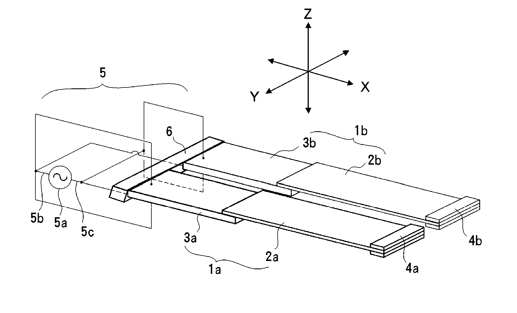
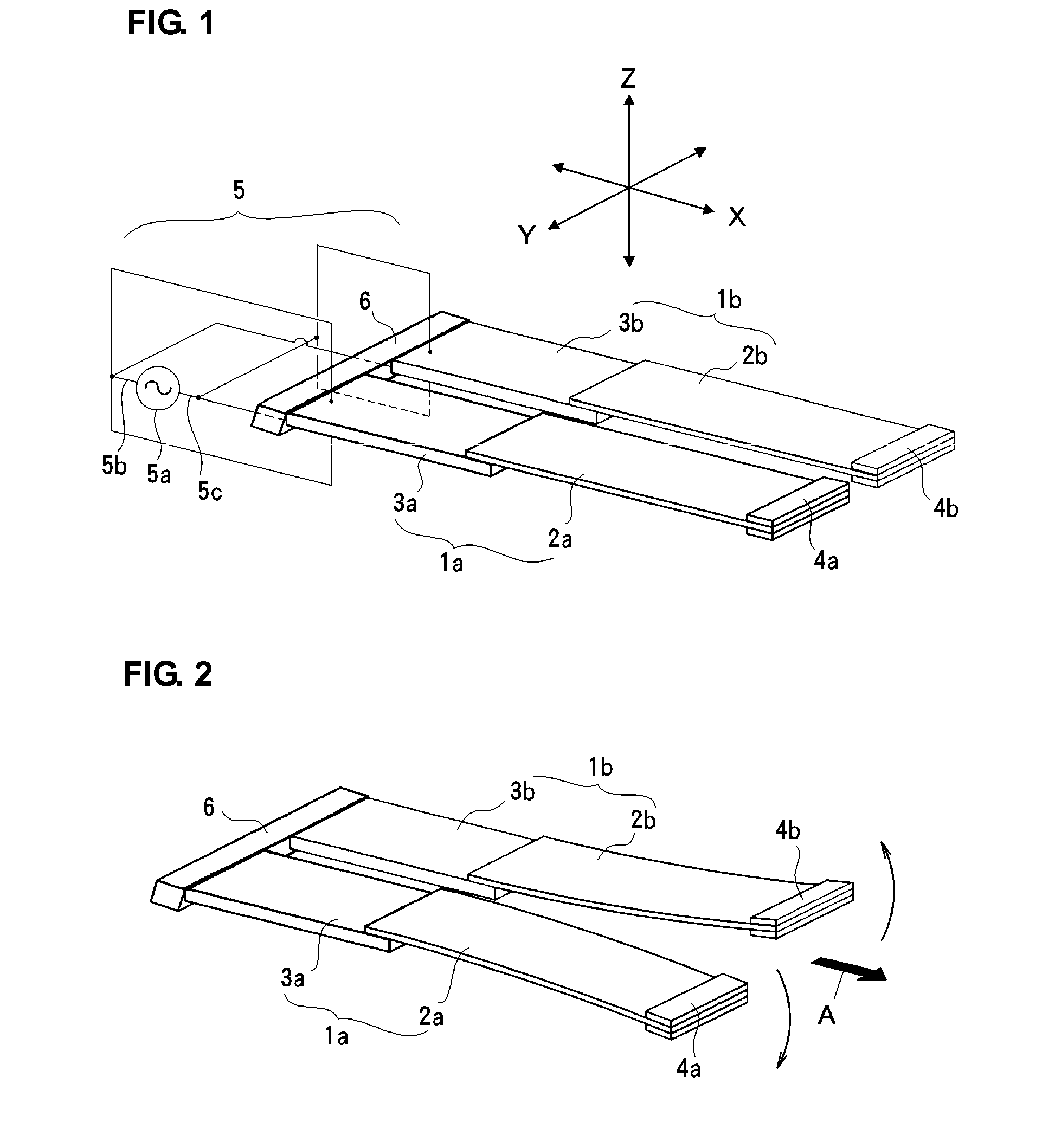
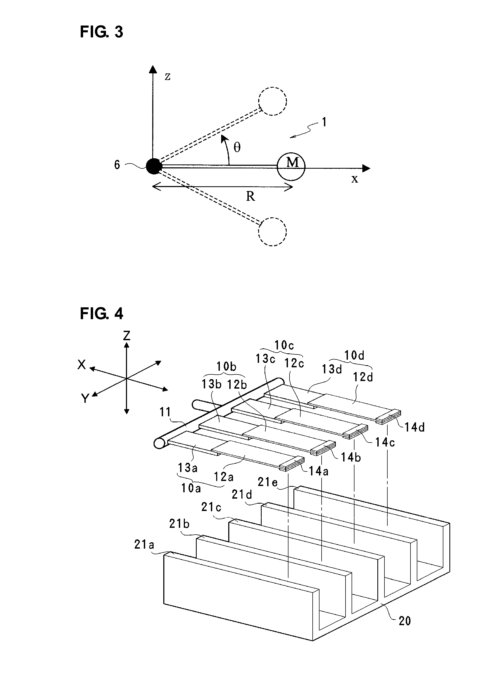
[0043]FIGS. 4 to 7 illustrate a piezoelectric fan device according to a first preferred embodiment of the present invention that is used as an air-cooling apparatus for a heat sink. In FIG. 4, four piezoelectric fans 10a to 10d having the same or substantially the same vibration characteristics are spaced uniformly in their thickness direction on a support 11 and coupled and fixed thereto. The piezoelectric fans 10a to 10d have substantially the same structure as the piezoelectric fans 1a and 1b illustrated in FIG. 1. That is, the piezoelectric fans 10a to 10d include blades 12a to 12d and bimorph piezoelectric vibrators 13a to 13d coupled to first ends of the blades 12a to 12d in their longitudinal direction, respectively. The blades 12a to 12d are capable of being freely flexurally displaced in their width direction. The piezoelectric vibrators 13a to 13d are flexurally vibrated when a voltage is applied. Weights 14a to 14d are fixed to free ends of the blades 12a to 12d, respecti...


PUM


Abstract

A piezoelectric fan device includes four piezoelectric fans that are arranged side-by-side in their width direction, and ends of the piezoelectric fans opposite to other ends in which the blades extend are coupled side-by-side and supported by a support. The piezoelectric fans include piezoelectric vibrators arranged to flexurally vibrate when a voltage is applied thereto and blades coupled to the piezoelectric vibrators such that the blades can be excited by the piezoelectric vibrators. Two central piezoelectric fans are driven in the same phase and the other two piezoelectric fans are driven in the opposite phase by a voltage applying device. Accordingly, not only vibrations of the centroid acting on the support but also moments about three axes are cancelled out.

Description

BACKGROUND OF THE INVENTION[0001]1. Field of the Invention[0002]The present invention relates to a piezoelectric fan device that produces wind using a blade that is flexurally displaced to a large extent by flexurally vibrating a piezoelectric vibrator coupled to the blade.[0003]2. Description of the Related Art[0004]Recently, for portable electronic equipment, with the advancement of miniaturization and high-density mounting of components, devices for dissipating heat generated inside the electronic equipment have become an issue. An example of a device that efficiently dissipates heat in such electronic equipment is an air-cooling apparatus that uses a piezoelectric fan.[0005]Japanese Unexamined Patent Application Publication No. 2-19700 discloses a piezoelectric fan that includes a piezoelectric bimorph vibrator including a pair of plate piezoelectric elements and a thin metal plate disposed therebetween and bonded thereto, a thin elastic plate is bonded to both ends of the piezo...

Claims


Application Information

Patent Timeline
Patent Type & Authority Applications(United States)
IPC IPC(8): F04B35/04
CPCF04D33/00
Inventor WADA, HIROAKIKAMITANI, GAKU
Owner MURATA MFG CO LTD
Learn More