
Method for the on-board functional diagnosis of a soot sensor in a motor vehicle and/or for the detection of further constituents in the soot

Inactive Publication Date: 2011-01-20
CONTINENTAL AUTOMOTIVE GMBH
View PDF12 Cites 12 Cited by
  • Summary
  • Abstract
  • Description
  • Claims
  • Application Information

AI Technical Summary

Benefits of technology

[0013]It is therefore an object of the invention to specify a method for functional diagnosis of a soot sensor and / or for detecting further components in the soot, by which it is possible to detect a faulty soot sensor and / or further components in the soot in an economical manner.
[0021]Carbon becomes a better conductor when heated than when cold. The bond between the valence electrons and the atomic nuclei is broken when thermal energy is supplied. This gives rise in each case to a free electron and a defect electron or electron hole. The electron hole carries a positive unit charge. The electron hole pair promotes current conduction when an electric voltage is applied. There is a dynamic equilibrium between pair formation and the re-combination thereof to give the uncharged atom. As the temperature rises, electron hole pair formation becomes easier and conductivity increases, i.e. resistance falls. Carbon and semiconductors are NTC resistors and have a negative temperature coefficient. At 20° C., carbon has the following temperature coefficient α, for example:α=−0.5·10−3 [K−1]

Problems solved by technology

If water, hydrocarbons, engine oil, abraded metallic material and / or ash components from burnt additives, for example, are present in the soot, this will result in a characteristic change in the temperature coefficient of the soot sensor.
As a consequence, the Brownian molecular motion increases and hinders the directional flow of current even more.

Method used


Image

  • Method for the on-board functional diagnosis of a soot sensor in a motor vehicle and/or for the detection of further constituents in the soot
  • Method for the on-board functional diagnosis of a soot sensor in a motor vehicle and/or for the detection of further constituents in the soot
  • Method for the on-board functional diagnosis of a soot sensor in a motor vehicle and/or for the detection of further constituents in the soot

Examples


Embodiment Construction

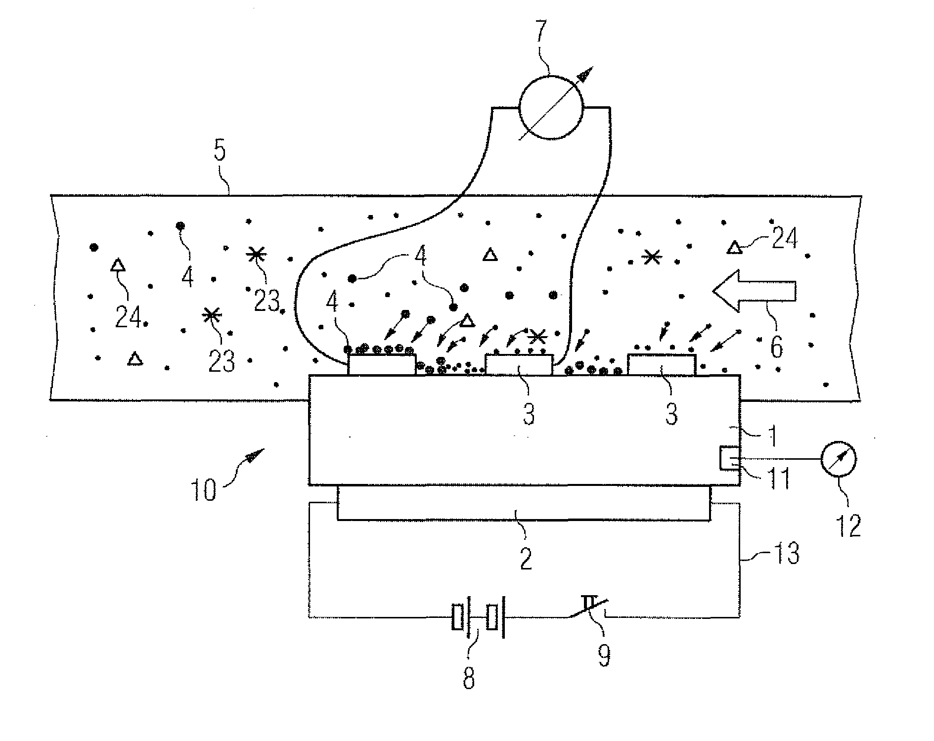
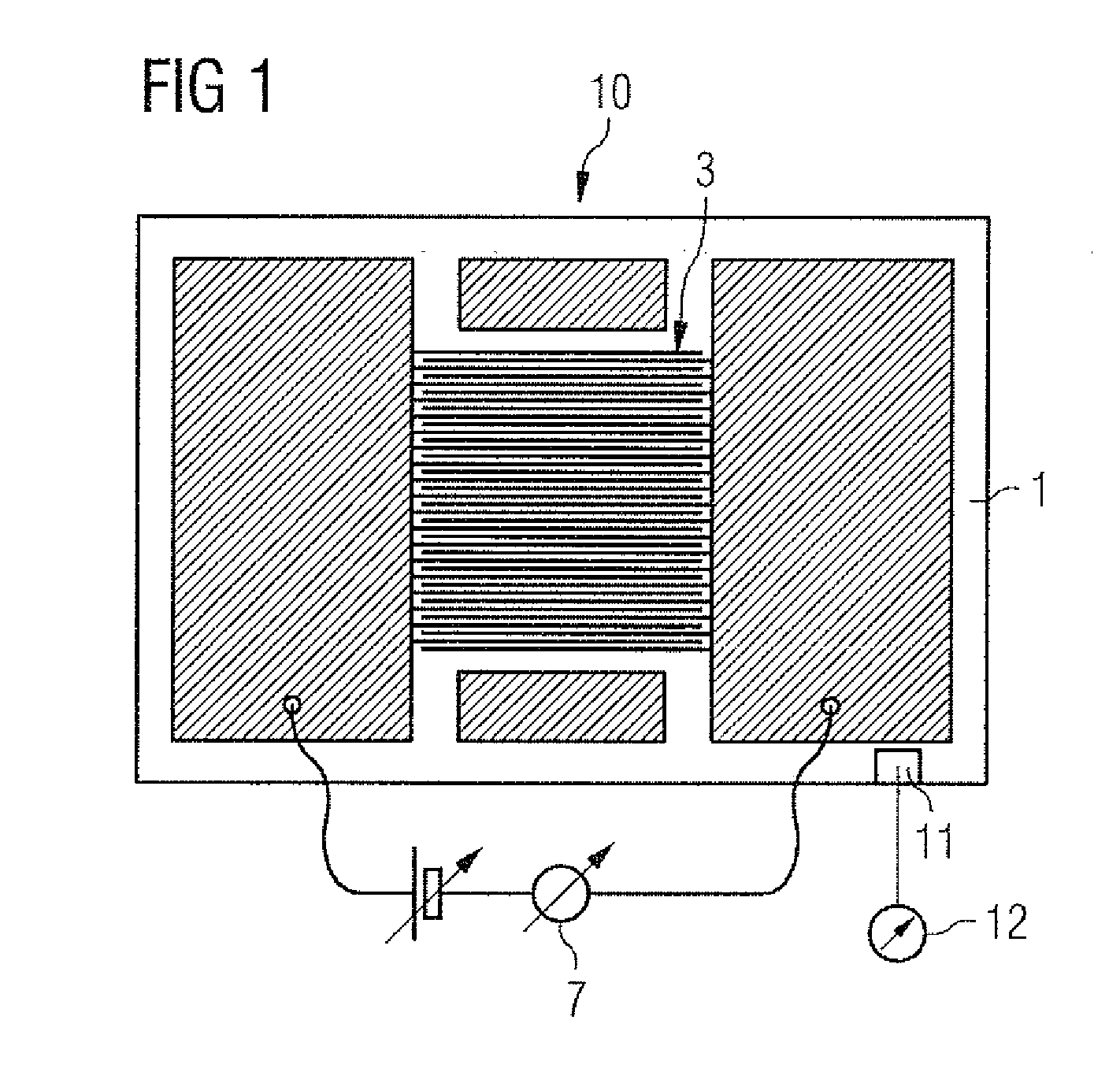
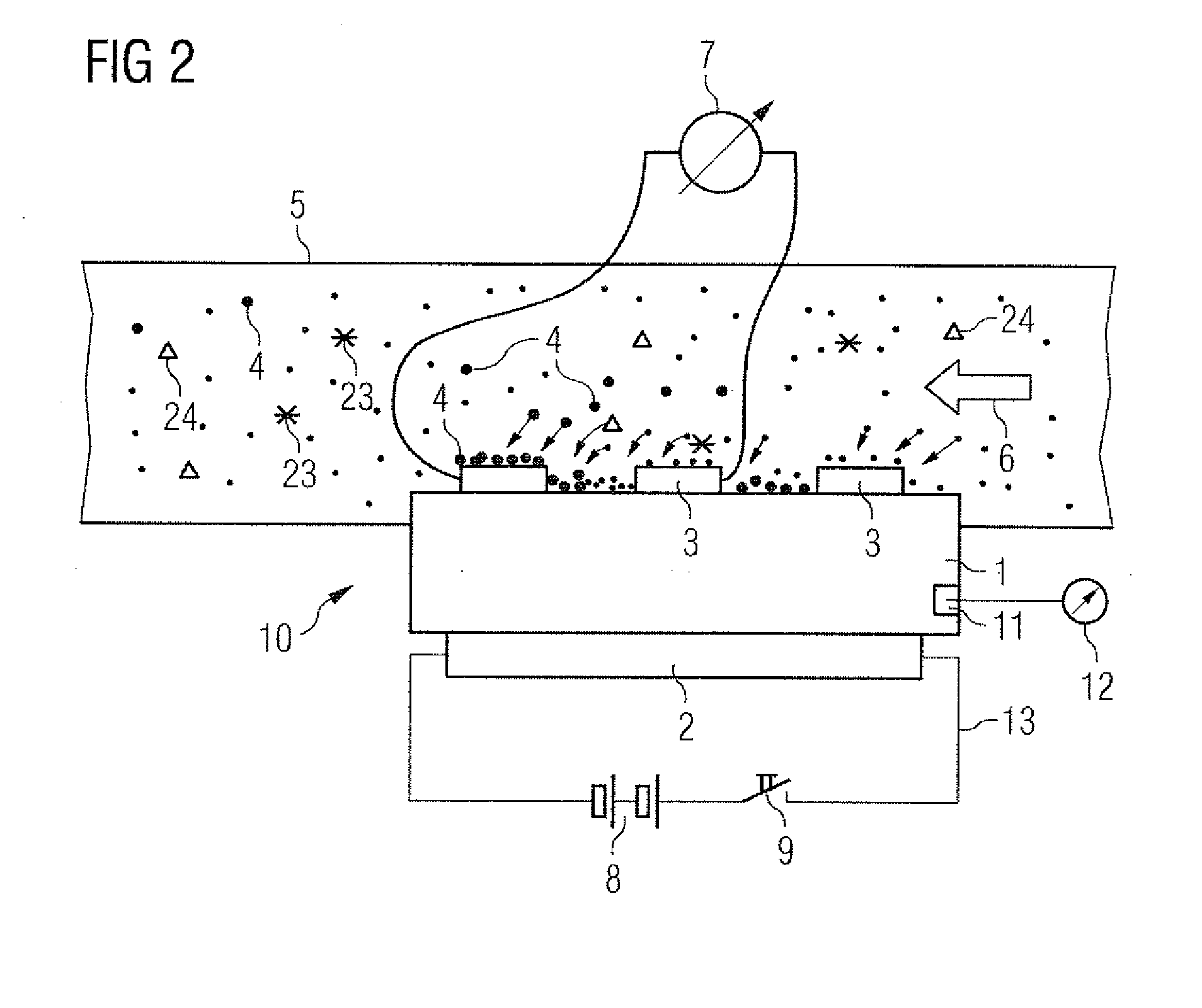
[0032]FIG. 1 shows a soot sensor 10, which is constructed from a molding 1, a heating element 2, and a structure consisting of measurement electrodes 3. The molding 1 can be produced from a ceramic material or from some other material that has electrically insulating properties and can easily withstand the burn-off temperature of soot. In order to burn off the soot from the soot sensor 10, the soot sensor 10 is typically heated to a temperature of between 500 and 800° C. by an electric resistance heater. The electrically insulating molding 1 must be able to withstand such temperatures without damage. Here, the structure of the measurement electrodes 3 is designed as a comb-type structure. An electrically insulating region of the molding 1 being visible between each two measurement electrodes 3. The flow of current from a voltage or current source between the electrode structures 3 is measured by a current measuring element 7. As long as the soot sensor 10 is completely free of soot ...


PUM


Abstract

A method for on-vehicle functional diagnosis of a soot sensor and / or for detecting further components in the soot in a motor vehicle having an internal combustion engine, the soot sensor connected electrically to an evaluation circuit. To specify a method for functional diagnosis of a soot sensor and / or for detecting further components in the soot, by which it is possible to detect a faulty soot sensor and / or further components in the soot in an economical manner, the evaluation circuit measures a temperature coefficient of the soot sensor and detects the faultiness of the soot sensor and / or the presence of further components in the soot from the temperature coefficient of the soot sensor.

Description

BACKGROUND OF THE INVENTION[0001]1. Field of the Invention[0002]The invention relates to a method for on-vehicle functional diagnosis of a soot sensor in a motor vehicle and / or for detecting further components in the soot, and to a soot sensor operated by this method, and to an evaluation circuit permanently installed in a motor vehicle having an internal combustion engine and intended for on-vehicle functional diagnosis of a soot sensor.[0003]2. Description of the Related Art[0004]There is currently a lot of discussion about the accumulation of pollutants from exhaust gases in the atmosphere. Along with this, the availability of fossil fuels is limited. One response to this is to thermodynamically optimize combustion processes in internal combustion engines to improve their efficiency. In the automotive sector, this is reflected in the increasing use of diesel engines. However, the disadvantage of this combustion technology relative to optimized spark-ignition engines is a signific...

Claims


Application Information

Patent Timeline
IPC IPC(8): G01M15/10
CPCF01N2560/05F02D41/1446F02D41/1466Y02T10/40F02D41/222G01N15/0656F02D41/1494
Inventor ANTE, JOHANNESBIERL, RUDOLFHERRMANN, MARKUSOTT, ANDREASREITMEIER, WILLIBALDSCHAEDLICH, DENNYWEIGL, MANFREDWILDGEN, ANDREAS
Owner CONTINENTAL AUTOMOTIVE GMBH
Learn More