
System and method for empirical ensemble- based virtual sensing

a virtual sensing and ensemble technology, applied in adaptive control, process and machine control, instruments, etc., to achieve the effect of improving the accuracy of the virtual sensor system according to the invention, avoiding extra work handling special cases, and being easy to implemen

Inactive Publication Date: 2011-01-13
INSTITUTT FOR ENERGITEKNIKK
View PDF7 Cites 10 Cited by
  • Summary
  • Abstract
  • Description
  • Claims
  • Application Information

AI Technical Summary

Benefits of technology

"The present invention is a virtual sensor system that solves problems of accuracy, robustness, stability, and simplicity. It uses a combination of empirical modelling and ensemble modelling to estimate virtual sensor output values from signal input values from sensors. The system includes two or more empirical models, each trained using empirical data and designed to calculate a signal output value based on the input values. The system also includes a combination function that receives the signal output values and calculates a virtual sensor output value as a function of the signal output values. The virtual sensor system can be used in real-time or near real-time measurements of critical parameters in industries such as energy and process."

Problems solved by technology

There has been several examples of unexpected and undesired discharges of oil in water from the oil industry, the discharges threatening the marine environment.
Faults related to any of the steps in the separation process, and especially the last step, may have serious consequences to the environment.
Continuous tuning related to the separation process or other systems based on the measurement values may not be possible.
There is thus a need for measuring the steam flow, but difficult to develop good sensors.
These could be air, water, oil, or material samples that are analysed to control environmental emission, discharge, product quality, or process condition.2. The available physical sensor is too slow, in particular for use in automatic control.3. The physical sensor is too far downstream, e.g the end product is continuously monitored to detect production deviations, but where this information comes too late to perform corrective action.4. The physical sensor is too expensive.5. There are no means of installing a physical sensor, e.g. no physical space.6. The sensor environment is too hostile.7. The physical sensor is inaccurate.
Available physical sensors might be subject to either intrinsic inaccuracies or to degradation.
Scaling in a Venturi flow-meter is a typical example.8. The physical sensor is expensive to maintain.
The main weakness of the analytical approach is that it requires accurate quantitative mathematical models in order to be effective.
For large-scale systems, such information may not be available or it may be too costly and time consuming to compile.
Accurate extrapolation, i.e. providing estimations for data that resides outside of the training data, is either not possible or not reliable for most empirical models.
When plant conditions or operations change significantly, the model is forced to extrapolate outside the learned space, and the results will be of low reliability.
Extrapolation, even if using a linear model, is not recommended for empirical models since the existence of pure linear relationships between measured process variables is not expected.
Furthermore, the linear approximations to the process are less valid during extrapolation because the density of training data in these extreme regions is either very low or non-existent.
Accordingly, the computational requirements lead to an upper limit on model size which is typically more limiting than that for other empirical model types.
When networks disagree: ensemble methods for hybrid neural networks, National Science Fundation, USA) Obviously, the combination of identical models would produce no performance gain.

Method used


Image

  • System and method for empirical ensemble- based virtual sensing
  • System and method for empirical ensemble- based virtual sensing
  • System and method for empirical ensemble- based virtual sensing

Examples


Embodiment Construction

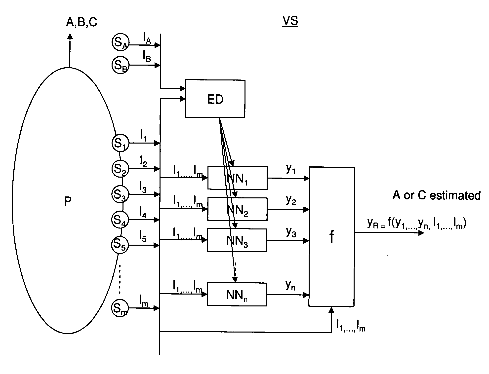
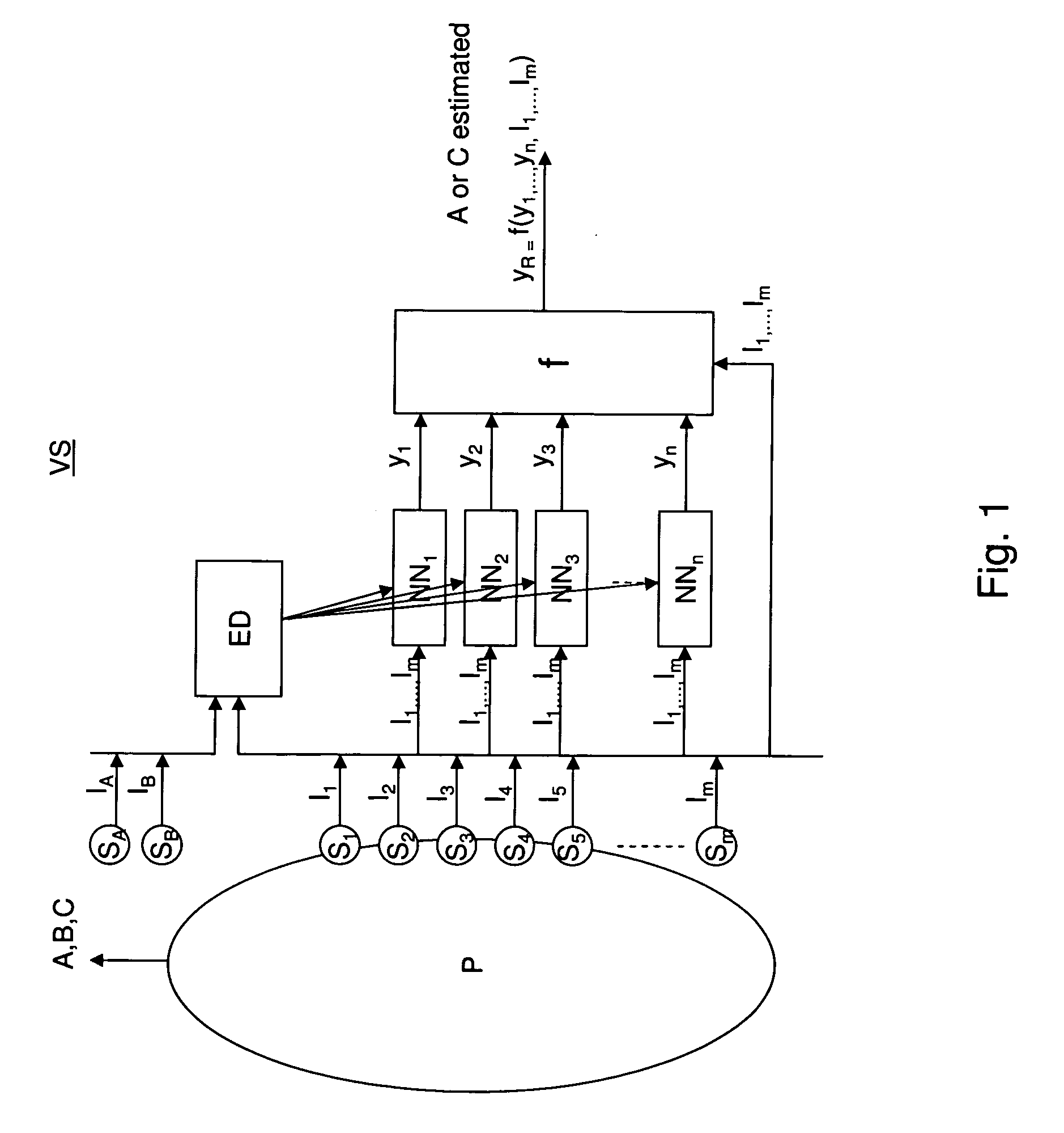
[0077]FIG. 1 is a block diagram of an embodiment of a virtual sensor system used to measure the amount (A,B,C) resulting from a process (P) according to the present invention.

[0078]In an embodiment the present invention the ensemble based virtual sensor system (VS) comprises two or more empirical models (NN1, NN2, . . . , NNn) where each of the empirical models (NN1, NN2, . . . , NNn) are arranged for estimating an intermediate result, and a combination function (f) is arranged for combining the intermediate results from the empirical models (NN1, NN2, . . . , NNn) to provide an estimation of the value that is more accurate than the signal output value (y1, y2, . . . , yn) from each of the individual empirical models (NN1, NN2 , . . . , NNn).

[0079]More specifically, in this embodiment of the invention each of the empirical models (NN1, NN2, . . . , NNn) are arranged for being trained using empirical data (ED). In an embodiment of the invention the empirical data are historical measu...


PUM


Abstract

An empirical ensemble based virtual sensor system (VS) for the estimation of an amount of water (C) or oil (A) in a fluid mixture, said virtual sensor comprising two or more empirical models (NN1, NN2, . . . , NNn). The amount is estimated in each of the empirical models (NN1, NN2, . . . , NNn), and a combination function combines (f) the results from the empirical models (NN1, NN2, . . . , NNn) to provide a combined estimate for the amount (yR) that is more accurate than the estimated amount (y1, y2, . . . , yn) from each of the individual empirical models (NN1, NN2, . . . , NNn). The total performance of the virtual sensor system may be increased by increasing the number of empirical models (NN1, NN2, . . . , NNn).

Description

[0001]This application is the National Phase of PCT / NO2008 / 000293 filed on Aug. 15, 2008, which claims priority under 35 U.S.C. 119(e) to U.S. Provisional Application Nos. 60 / 935,548 filed on Aug. 17, 2001, all of which are hereby expressly incorporated by reference into the present application.TECHNICAL FIELD [0002]The present invention relates to a method and system for empirical ensemble-based virtual sensing and more particularly to a method and system for virtual sensors for measuring parameters from the energy sector and process industry, such as an amount of oil in discharged water or a mass flow rate of a steam used to drive a turbine in a power plant.BACKGROUND [0003]Discharges to sea and emissions to air from the oil and gas industry are of major concern to the quality of air and water. There has been several examples of unexpected and undesired discharges of oil in water from the oil industry, the discharges threatening the marine environment. In that respect the environm...

Claims


Application Information

Patent Timeline
Patent Type & Authority Applications(United States)
IPC IPC(8): G06F15/18G05B13/02
CPCF01N9/005Y02T10/47G06N3/0454Y02T10/40G06N3/045
Inventor ROVERSO, DAVIDE
Owner INSTITUTT FOR ENERGITEKNIKK
Learn More