
Vehicular steering control apparatus

a control apparatus and steering control technology, applied in the direction of steering initiation, instruments, vessel construction, etc., can solve the problems of limiting the applied voltage by the upper limit value, unable to cancel the back electromotive force, and affecting the steering operation of the driver, so as to suppress the effect of decreasing the handling

Inactive Publication Date: 2011-01-13
TOYOTA JIDOSHA KK
View PDF8 Cites 22 Cited by
  • Summary
  • Abstract
  • Description
  • Claims
  • Application Information

AI Technical Summary

Benefits of technology

The invention provides a steering control apparatus and method for vehicles that can prevent a decrease in handling when there is an upper limit to the driving voltage of the motor. This is achieved by controlling the driving voltage to apply assist steering force based on the steering amount of a predetermined kind, and reducing the amount of power generated by the motor when it is determined to be in a power generating state. The steering control apparatus includes a first control apparatus that controls the driving voltage to apply the assist steering force, a determining apparatus that determines whether the motor is in a power generating state, and a second control apparatus that reduces the amount of power generated by the motor when it is determined to be in a power generating state. The driving voltage is set so as to equal or less than a predetermined upper limit voltage, which is determined by the configuration or structure of the motor or the drive apparatus. This invention can improve the stability and responsiveness of the vehicle's steering system.

Problems solved by technology

Therefore, even if the applied voltage (which is one form of the driving voltage in this case) is corrected simply taking the back electromotive force into account as it is in the related art, the applied voltage is limited by the upper limit value and therefore may not be able to cancel the back electromotive force.
That is, with the related art there is the technical drawback that a steering operation by the driver may be impeded when the driving voltage of the motor is limited by the upper limit value.

Method used


Image

  • Vehicular steering control apparatus
  • Vehicular steering control apparatus
  • Vehicular steering control apparatus

Examples


Embodiment Construction

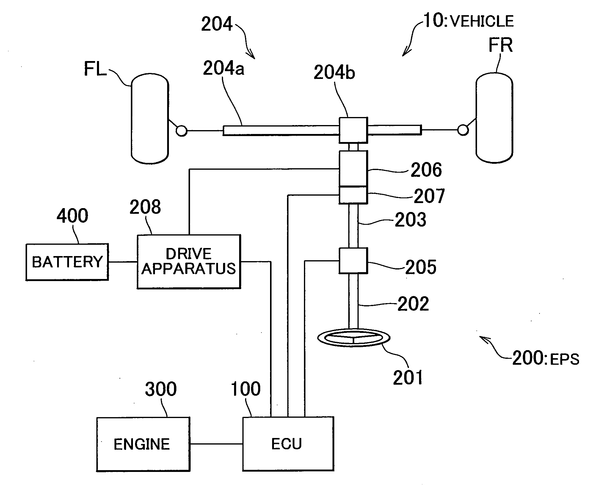
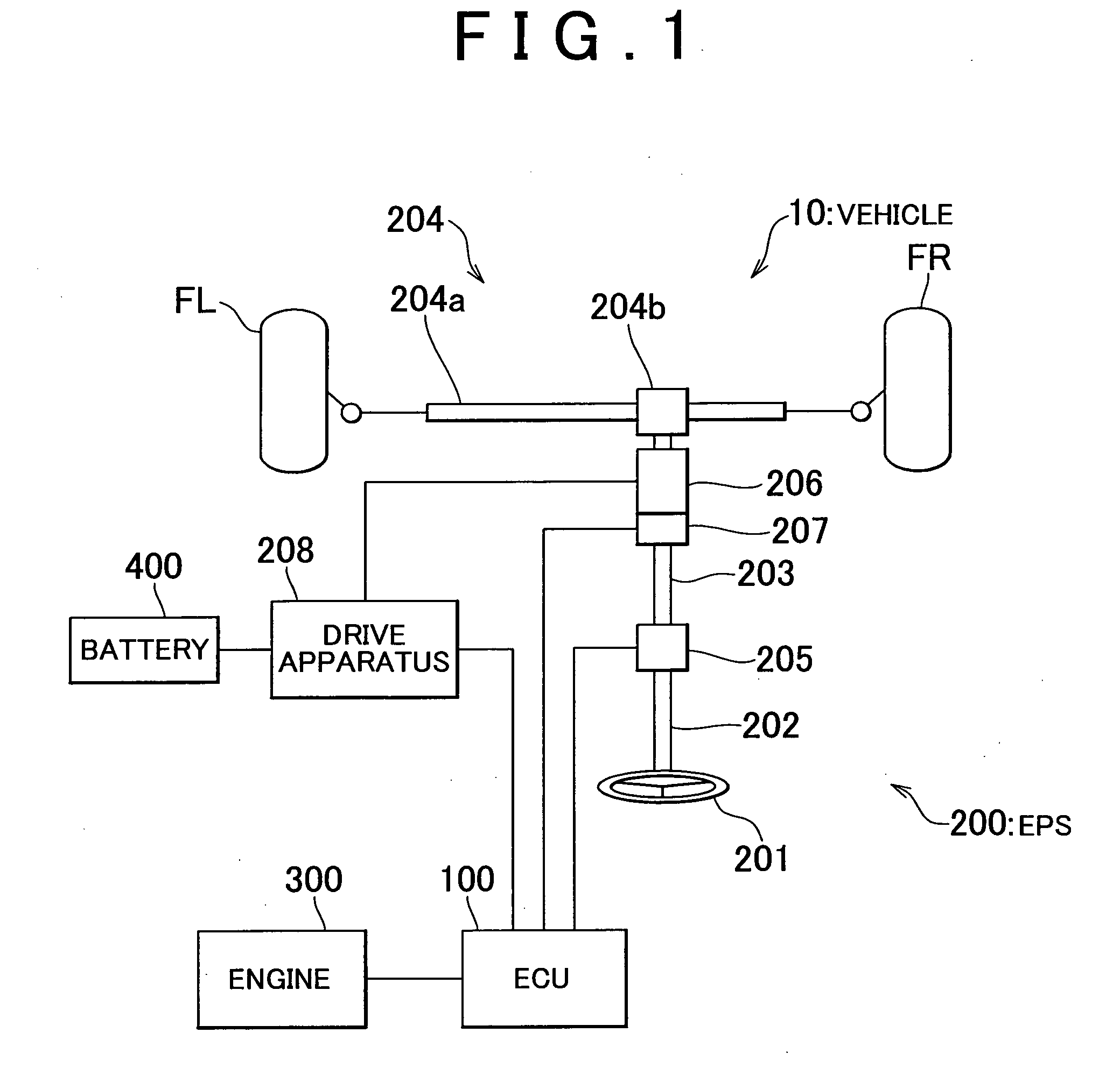
[0059]Hereinafter, various example embodiments relating to the vehicular steering control apparatus of the invention will be described with reference to the drawings when appropriate. First, the structure of a vehicle 10 according to a first example embodiment of the invention will be described with reference to FIG. 1, which is a schematic diagram conceptually showing the basic structure of the vehicle 10.

[0060]In FIG. 1, the vehicle 10 has a pair of left and right front wheels FL and FR, which are the steered wheels, and is structured so as to be able to move in a desired direction by these front wheels being steered.

[0061]The vehicle 10 includes an ECU 100, an EPS 200, and an engine 300.

[0062]The ECU 100 is an electronic control unit that includes a CPU (Central Processing Unit), ROM (Read Only Memory), and RAM (Random Access Memory), none of which are shown, and controls the overall operation of the vehicle 10. The ECU 100 is one example of a steering control apparatus of a vehi...


PUM


Abstract

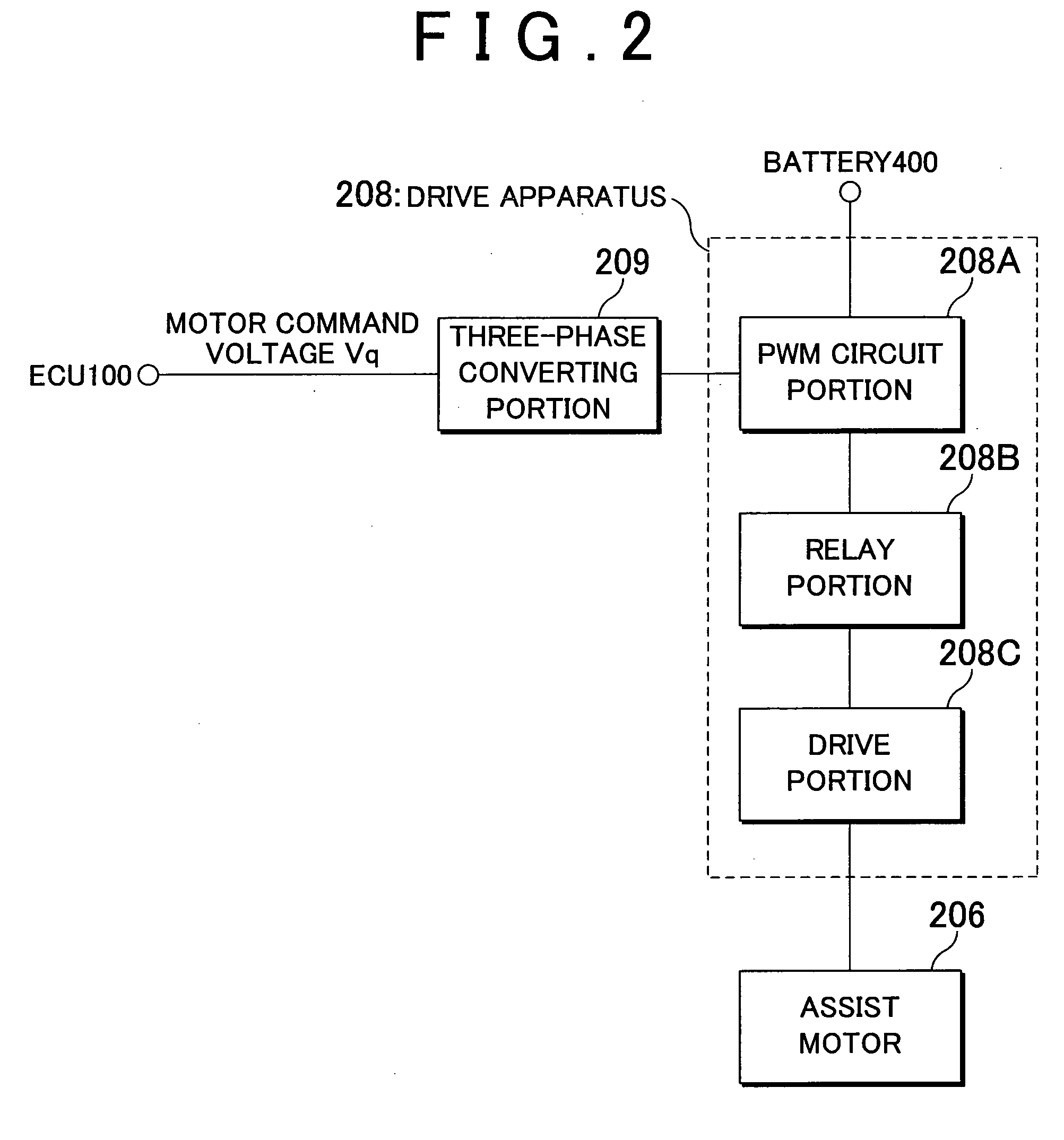
An ECU executes steering control in a vehicle including an electronic control power steering apparatus. In the steering control, it is determined that an assist motor is in a power generating state when a motor rotation speed ω which is the rotation speed of the assist motor is greater than an upper limit rotation speed ω1 set according to a motor command voltage Vq that is the driving voltage of the assist motor. When the assist motor is in the power generating state, the ECU interrupts the supply of current to the assist motor by controlling a relay portion of a drive apparatus that drives the assist motor so that it is open, thereby reducing the amount of power that is generated to zero. Also, when returning to an assist possible state, assist torque Tm is changed gradually with zero as the initial value in order to prevent it from changing suddenly.

Description

BACKGROUND OF THE INVENTION[0001]1. Field of the Invention[0002]The invention relates to the technical field of a steering control apparatus and steering control method for a vehicle provided with an electric power steering apparatus such as EPS (Electronic controlled Power Steering).[0003]2. Description of the Related Art[0004]Japanese Patent Application Publication No. 6-211142 (JP-A-6-211142), for example, proposes one type of electric power steering apparatus that takes the back electromotive force of an electric motor into account. The electric power steering apparatus described in JP-A-6-211142 (hereinafter referred to as the “related art”) enables good steering feel to be obtained by calculating the back electromotive force of the electric motor based on the detected rotation speed of the electric motor, and correcting the applied voltage of the electric motor based on that calculated back electromotive force.[0005]Incidentally, Japanese Patent Application Publication No. 200...

Claims


Application Information

Patent Timeline
Patent Type & Authority Applications(United States)
IPC IPC(8): B62D6/00B62D5/04
CPCB62D5/0481B62D5/046
Inventor LIMPIBUNTERNG, THEERAWATKOJO, TAKAHIRO
Owner TOYOTA JIDOSHA KK
Learn More