
Robot control system

a robot control and control system technology, applied in the field of robot control systems, can solve the problems of affecting the operation of the operator, affecting the operation of the program, and the charging amount of the secondary battery of the portable operating device tp decreases as the time elapses

Active Publication Date: 2011-01-13
DAIHEN CORP +1
View PDF11 Cites 45 Cited by
  • Summary
  • Abstract
  • Description
  • Claims
  • Application Information

AI Technical Summary

Benefits of technology

[0014]In this configuration, if it is detected that an electric connection between the portable operating device and the robot control device has not been established when the robot is in automatic operation, the wireless communication is ended and the automatic operation of the robot is continued solely through the robot control device without causing an emergency stop of the robot with the portable operating device disconnected from the robot control system. In this manner, the automatic operation of the robot is continuously performed without having to considering whether or not the portable operating device is connected to the charging device. This improves work efficiency. Further, since the automatic operation of the robot is continued solely through the robot control device without carrying out wireless communication, an emergency stop of the robot, which may be caused by communication noise, does not occur. Also, after having been disconnected from the robot control system, the portable operating device may be used for robot teaching in an additional robot control system.
[0020]This configuration includes a disconnection detecting section that detects whether the portable operating device is disconnected from the robot control system and a display means that displays a message informing the reader that the portable operating device is disconnected from the robot control system. This allows the operator to know whether the portable operating device has been disconnected from the robot control system and automatic operation of the robot continues.
[0022]This configuration includes a date / time obtaining section that obtains the date and time of when the portable operating device was disconnected from the robot control system and / or the charging amount obtaining section that obtains the charging amount of the secondary battery at the time when the portable operating device is disconnected from the robot control system. The display means displays at least one of the date / time and the charging amount at the time when the portable operating device is disconnected. This allows the operator to know the specific condition at the time when the portable operating device is disconnected from the robot control system.

Problems solved by technology

The connection cable thus may hamper operation by the operator.
This prevents interruption of communication between the portable operating device TP and the robot control device RC due to insufficient charging of the secondary battery, which leads to an emergency stop of the robot R and thus interruption of the production line.
However, if the automatic operation of the robot R is continuously performed despite the alarm, the charging amount of the secondary battery of the portable operating device TP decreases as the time elapses.
Such a connecting operation is troublesome for the operator.
Further, the portable operating device is necessary mainly for robot teaching but unnecessary for the automatic operation of the robot.
However, when a single robot control device has to be connected to a single portable operating device, as in the case of the robot control system disclosed in Patent Document 1, the portable operating device cannot be used to operate other robot control systems.Patent Document 1: Japanese Laid-Open Patent Publication No. 2006-341356

Method used


Image

  • Robot control system
  • Robot control system
  • Robot control system

Examples


first embodiment

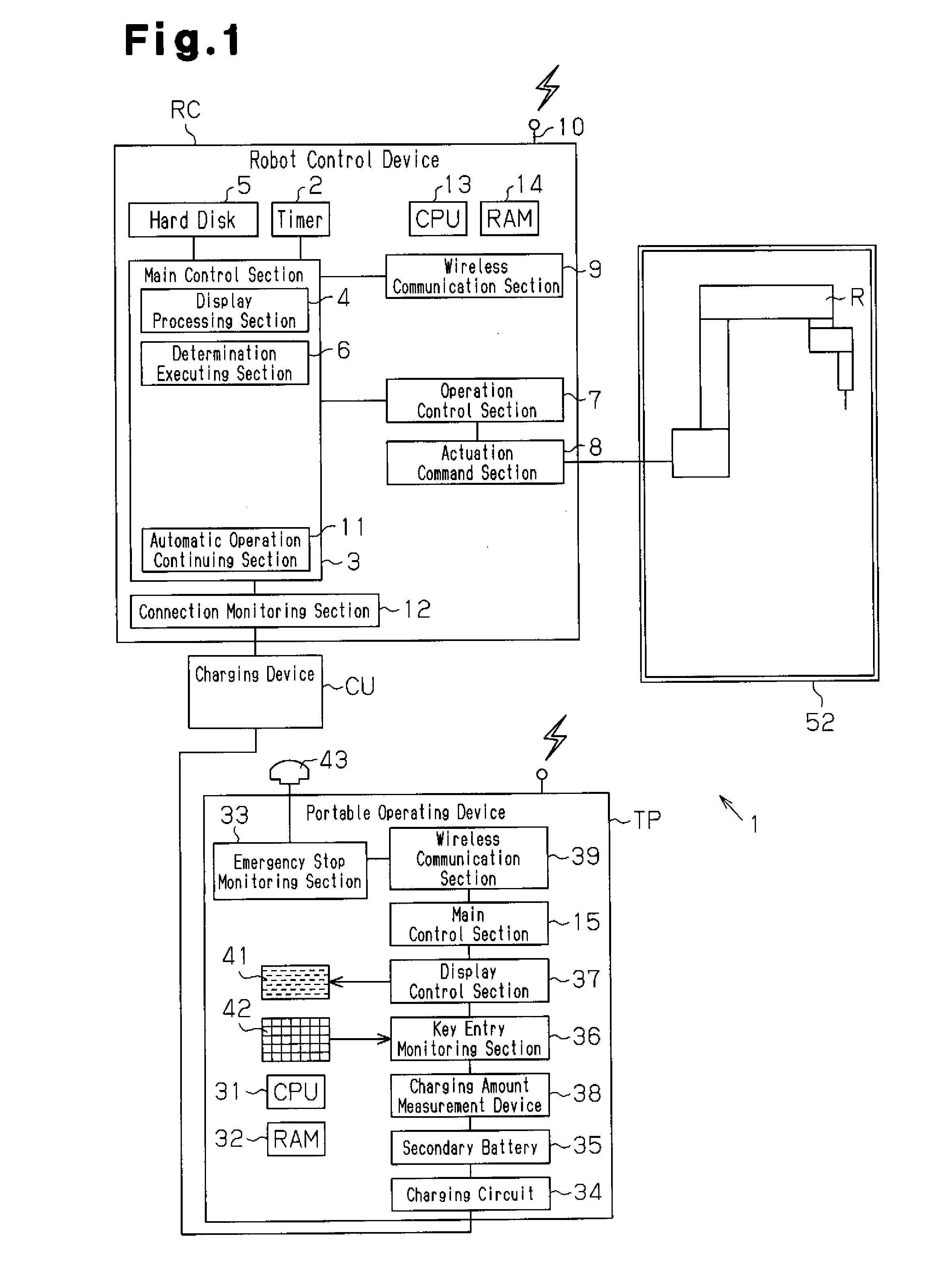
[0029]One embodiment of a robot control system according to the present invention will now be described with reference to FIG. 1.

[0030]As illustrated in FIG. 1, a robot control system 1 includes a robot control device RC for controlling operation of a robot R, the robot R installed in the space surrounded by a safety fence 52, a portable operating device TP for operating the robot R, and a charging device CU for charging the portable operating device TP. Wireless communication can be carried out between the portable operating device TP and the robot control device RC. An emergency stop of the robot R is caused when wireless communication is temporarily interrupted by noise generation or insufficient radio field intensity as the wireless communication is carried out.

[0031]The robot control device RC includes a CPU 13 serving as a central processing unit, a RAM 14 serving as a temporary calculation area, a system timer 2, a main control section 3 serving as a control center, a hard di...

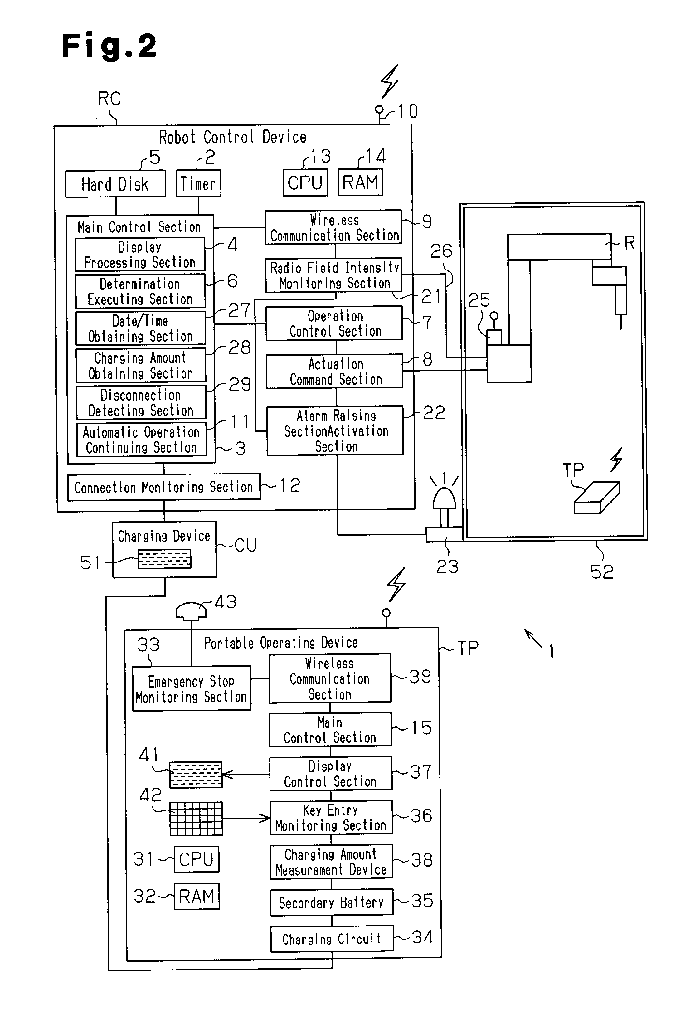
second embodiment

[0040]A second embodiment of the present invention will hereafter be described with reference to FIG. 2. Detailed description of components of the second embodiment that are the same as or like corresponding components of the first embodiment will be omitted herein. The second embodiment is configured identically with the first embodiment except for an alarm lamp 23 serving as alarm activation means, a radio field intensity measurement device 25 mounted in the vicinity of the robot R, a connection cable 26, a display section 51 arranged in the charging device CU, a radio field intensity monitoring section 21, an alarm activation section 22, a date / time obtaining section 27, a charging amount obtaining section 28, and a disconnection detecting section 29. The radio field intensity monitoring section 21, the alarm activation section 22, the date / time obtaining section 27, the charging amount obtaining section 28, and the disconnection detecting section 29 are provided in the robot con...


PUM


Abstract

A robot control system has a portable operating device TP and a robot control device RC. The portable operating device TP is actuated by a rechargeable secondary battery and used to operate a robot R. The robot control device RC is capable of wireless communication with the portable operating device TP and performs automatic operation of the robot R based on teaching data provided by the portable operating device TP. The robot control system causes an emergency stop of the robot R when the wireless communication between the portable operating device TP and the robot control device RC is interrupted. The robot control system further includes a charging device CU, a connection monitoring section 12, and an automatic operation continuing section 11. The charging device CU charges the secondary battery by electrically connecting the portable operating device TP to the robot control device RC. The connection monitoring section 12 monitors whether connection between the portable operating device TP and the robot control device RC through the charging means is established. Even if it is detected that the aforementioned connection is not established when the robot R is in automatic operation, the automatic operation continuing section 11 ends wireless communication without causing an emergency stop of the robot R and continues automatic operation of the robot R solely through the robot control system RC.

Description

TECHNICAL FIELD[0001]The present invention relates to a robot control system that transmits and receives various types of data through wireless communication between a robot control device and a portable operating device.BACKGROUND ART[0002]In a conventional robot control system, a robot control device for controlling a robot and a portable operating device performing operations for teaching the robot are electrically connected to each other via a connection cable. The connection cable transmits teaching data or setting data for teaching the robot from the portable operating device to the robot control device. The connection cable also transmits display data from the robot control device to the portable operating device so that the display data is displayed on a display of the potable operating device.[0003]The connection cable is dragged around by the operator who carries the portable operating device when the operator teaches the robot. The connection cable thus may hamper operati...

Claims


Application Information

Patent Timeline
Patent Type & Authority Applications(United States)
IPC IPC(8): B25J9/00
CPCB25J9/1674B25J19/06B25J13/06
Inventor TANI, NOBUHIROKOUJINA, YASUHIRONAKATSUGAWA, YUJI
Owner DAIHEN CORP
Learn More