Purification assembly having catalysts for gases and combustion fumes from solid fuel heating apparatus

a technology of purification assembly and catalyst, which is applied in the direction of combustion using catalytic materials, combustion types, separation processes, etc., can solve the problems of difficult temperature attainment, inability to post-combustion process, and failure of catalysts to activate during certain phases of operation, etc., to enhance the life expectancy of the device, improve the effect of energy balance and simple design

Inactive Publication Date: 2011-01-13
FONDIS SA
View PDF5 Cites 19 Cited by
  • Summary
  • Abstract
  • Description
  • Claims
  • Application Information

AI Technical Summary

Benefits of technology

[0012]Whereas in the prior art, a diversion outlet was provided for combustion gases and fumes during the transitory fire startup and extinguishing phases for preventing rapid contamination, according to the present invention, the combustion gases and fumes pass through only this catalytic device; and it further comprises, close to and upstream of the direction in which the gases and fumes are evacuated, a rapid heating means to raise the catalyst to a high temperature, thus engaging the catalytic reaction during all phases of operation, even at lower temperatures that are more likely to contaminate the catalyst.
[0017]The simple design considerably enhances the life expectancy of the device.
[0018]Since the catalytic reaction is exothermal, there is a positive energy balance.

Problems solved by technology

Unfortunately, temperatures that are too low may result in these catalysts failing to activate during certain phases of operation, specifically during the transitory phases when the fire is being started up or extinguished.
In actuality, with many pollutants, the catalytic reaction begins at around 400° C., a temperature difficult to attain at the furnace outlet, especially during transitory phases.
Unfortunately, there is a variable quantity of non-combusted material and the post-combustion process may not be not capable at any given moment of furnishing the supplemental calories necessary to start and sustain the process up to the permanent catalysis phase.
This rather random operation cannot guarantee that the gases and fumes evacuated through the flue will be constantly purified, nor is it possible to position a catalytic cell that would fill the entire space of the combustion gas and fume duct because contamination builds up quickly at lower burn rates.

Method used


Image

  • Purification assembly having catalysts for gases and combustion fumes from solid fuel heating apparatus
  • Purification assembly having catalysts for gases and combustion fumes from solid fuel heating apparatus
  • Purification assembly having catalysts for gases and combustion fumes from solid fuel heating apparatus

Examples


Embodiment Construction

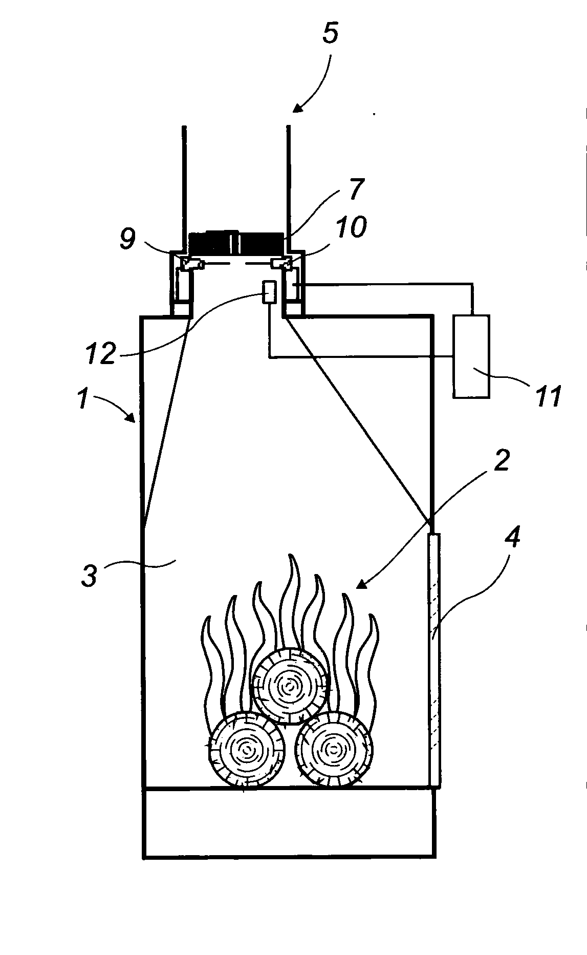
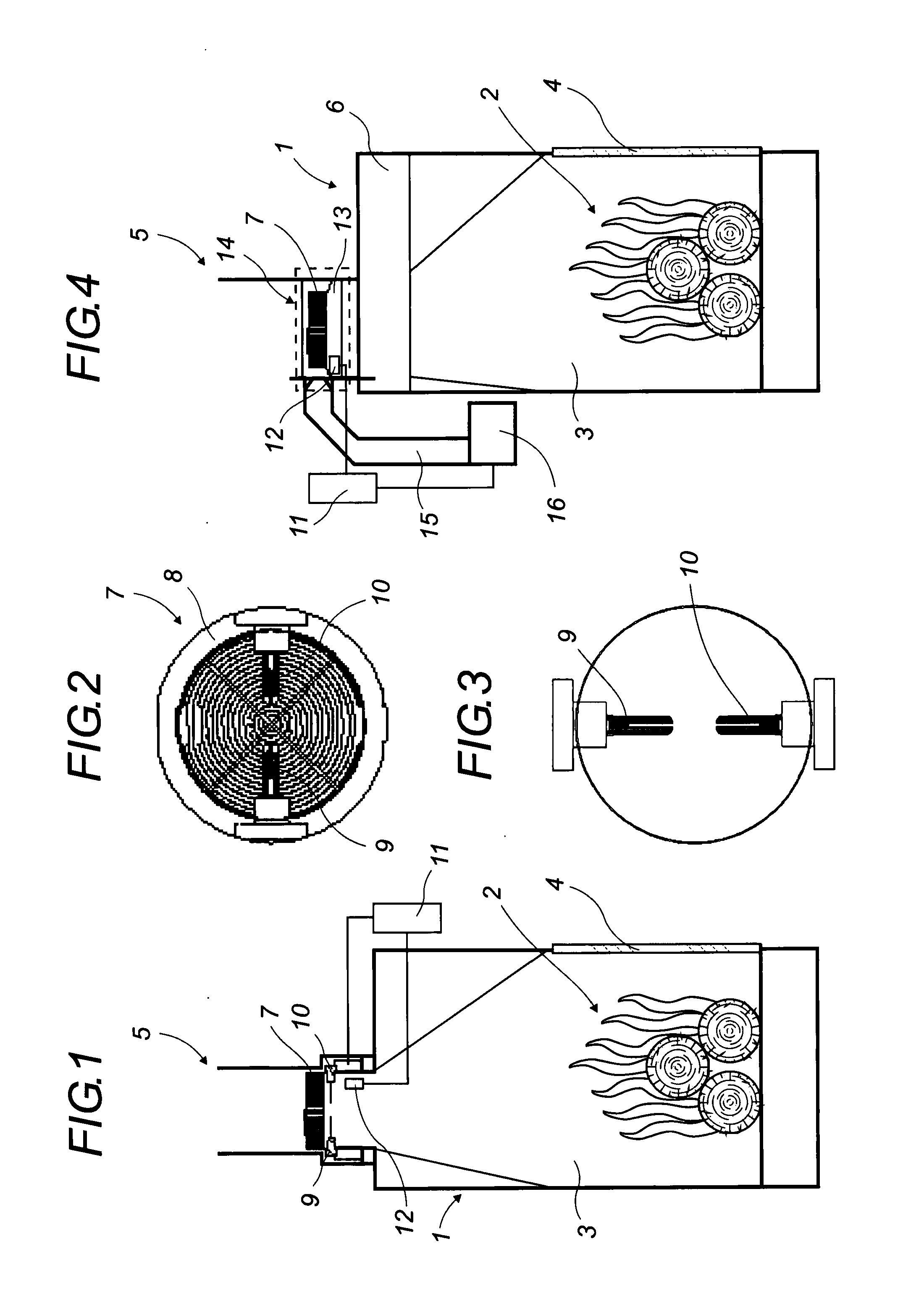
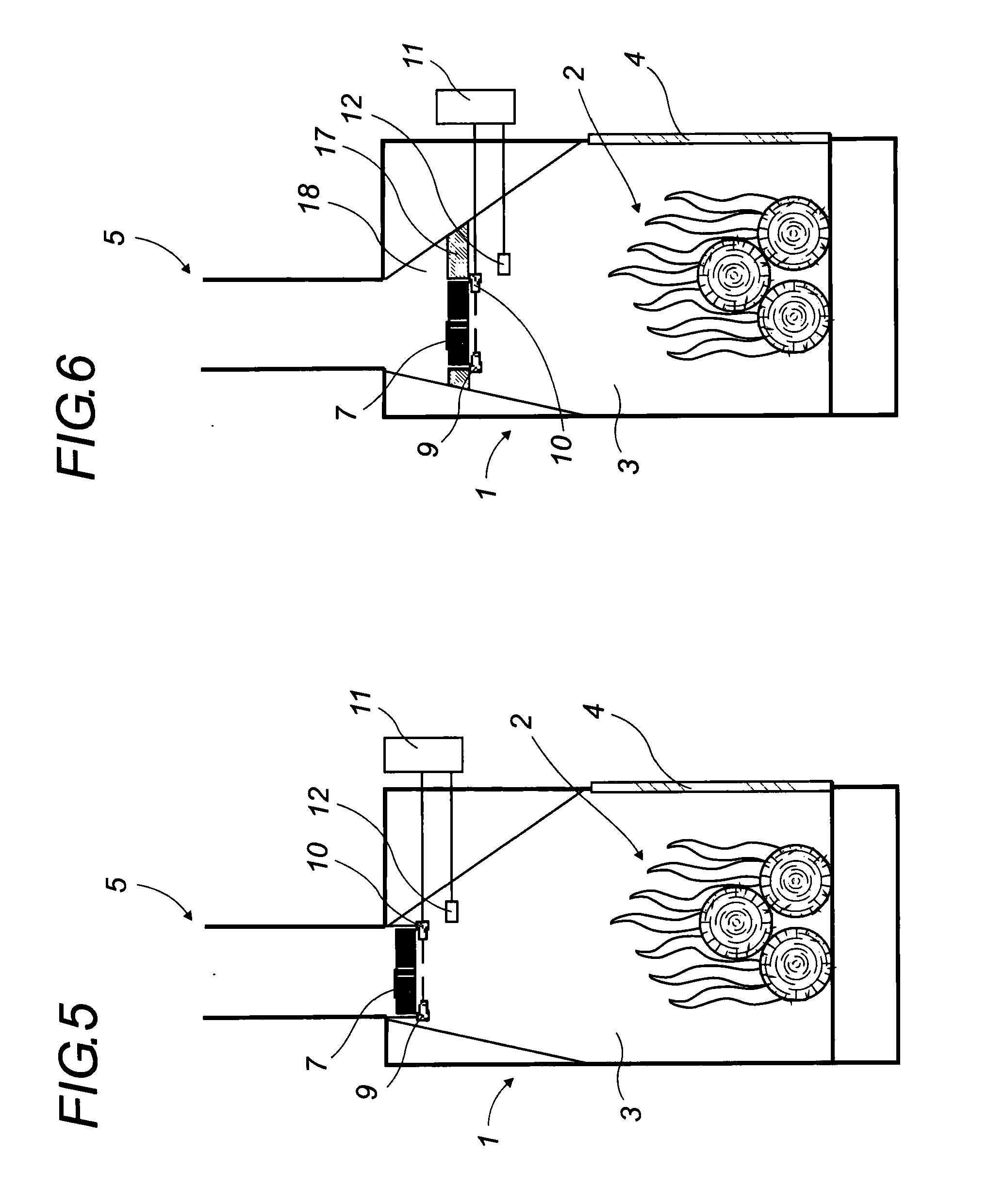
[0028]The present invention applies to a solid fuel heating apparatus such as a stove or a closed chimney furnace with an insert 1, having a furnace 2, a combustion chamber 3, a glass door 4, and an exhaust duct 5 for gas and combustion fumes. The duct 5 may be a continuation of a smoke box 6 with or without a heat exchanger or connect directly to a vent.

[0029]In this exhaust duct 5 at the outlet of the smoke box or the vent, the catalyst device 7 is placed, for example, at its source, in the form of a body 8 generally made of ceramic or metal, completely filling the interior of the exhaust duct and traversed completely and uniquely by the combustion gases and fumes.

[0030]The combustion gases and fumes have no outlet other than through catalyst device 7, even during the transitory phases of starting or extinguishing the fire.

[0031]When placed in the flue, the body 8 of catalyst device 7 assumes the same or approximately the same shape as the flue. Its interior space is formed of a p...


PUM

PropertyMeasurementUnit
temperatureaaaaaaaaaa

Abstract

An assembly for purifying the gases and combustion fumes from a heating apparatus, particularly from a closed chimney furnace of the type using a catalyst device (7) in the gas and combustion fume exhaust duct (5). The assembly has an electrically powered rapid acting heater for raising the temperature, in and / or near the catalyst device (7), to initiate a catalytic reaction. A temperature-sensitive sensor or detector (12) is provided in the control circuit (11) of the heater. The assembly is of interest to builders of heating apparatuses using solid fuel, particularly wood.

Description

[0001]This application is a National Stage completion of PCT / FR2009 / 000301 filed Mar. 20, 2009, which claims priority from French patent application Ser. No. 08 / 01535 filed Mar. 20, 2008.FIELD OF THE INVENTION[0002]The invention relates to a catalytic assembly used to purify combustion gases and fumes from a solid fuel heating apparatus, particularly a high output wood heating apparatus, during all phases of operation.[0003]This assembly contains a heated catalyst placed near or at the outlet at its upper portion and constituting the only outlet for combustion gas and fumes.[0004]The catalyst is brought to a high temperature by an electrically charged rapid heating device for oxidizing, catalyzing or calcinizing gaseous pollutants and particles present in the gases and combustion fumes from a solid fuel heating apparatus, for example, a closed furnace in a wood burning heater. The catalyst constitutes the only possible passageway for combustion gases and fumes.BACKGROUND OF THE INVE...

Claims


Application Information

Patent Timeline
Patent Type & Authority Applications(United States)
IPC IPC(8): B01D53/34
CPCB01D53/74B01D53/8678B01D53/885F23J2219/10F23G7/07F23J15/02F23C13/02
Inventor HAAS, FREDERICOZIL, FABIENTSCHAMBER, VALERIETROUVE, GWENAELLE
Owner FONDIS SA
Why Eureka
Try Eureka