
Crane control for the control of a hoisting gear of a crane

a crane and hoisting gear technology, applied in the direction of load-engaging elements, transportation and packaging, etc., can solve the problem of substantial dynamic loads and achieve the effect of improving crane control

Active Publication Date: 2011-01-13
LIEBHERR WERK NENZING
View PDF6 Cites 12 Cited by
  • Summary
  • Abstract
  • Description
  • Claims
  • Application Information

AI Technical Summary

Benefits of technology

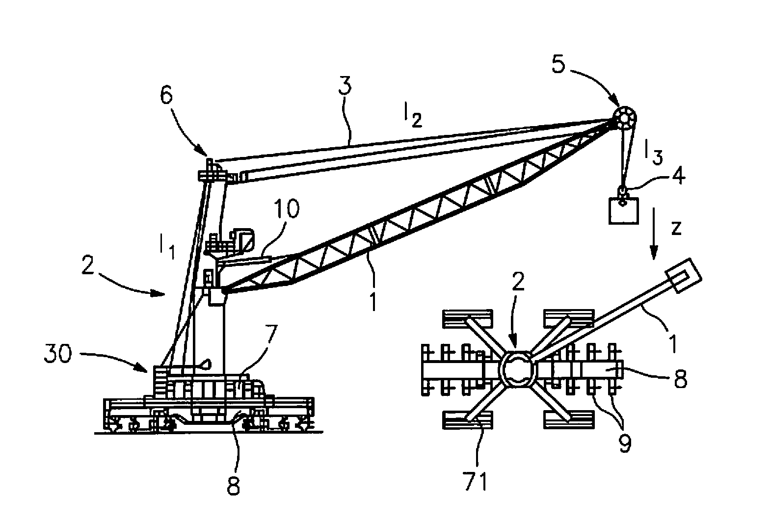
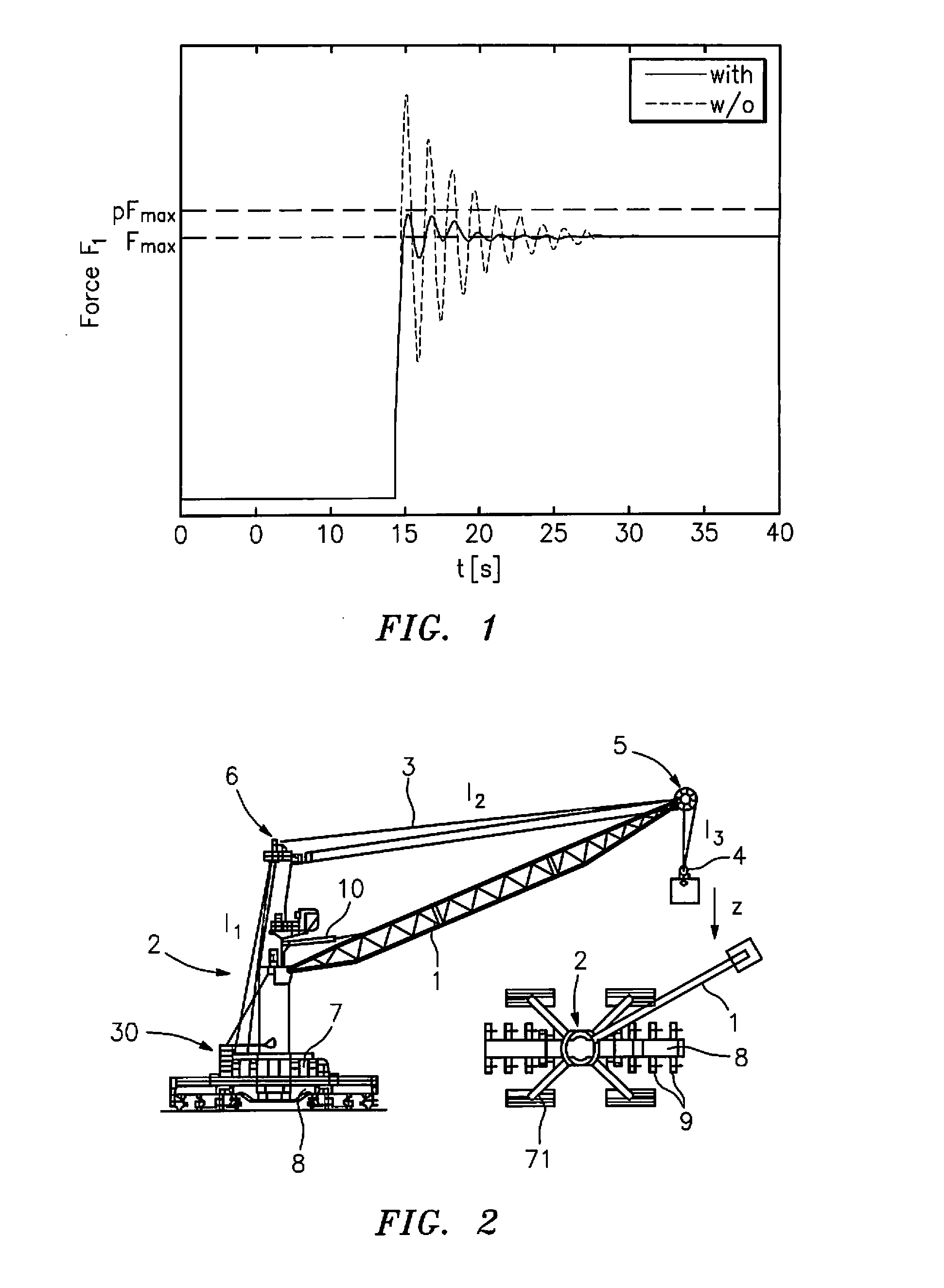
[0005]This object is satisfied in accordance with the invention by a crane control in accordance with the description herein. The present invention thus provides a crane control for the control of a hoisting gear of a crane which takes account of the oscillation dynamics based on the elasticity of the hoist rope in the control of the hosting gear and reduces or damps them by a suitable control of the hoisting gear. The oscillation dynamics of the system of rope and load is in this respect in particular taken into account. Further advantageously, the hoisting gear and / or the crane structure can also be taken into account. It is hereby possible to reduce the dynamic loads, which act on the rope and the crane structure, by use of the crane control in accordance with the invention. The crane structure can hereby be built correspondingly lighter or can be operated with higher static loads. The crane control in accordance with the invention can in this respect in particular limit the hosting force acting on the crane structure to a maximum permitted value by taking account of the oscillation dynamics of the system of hoisting gear, rope and load.
[0035]The control of the hoisting gear in this respect advantageously takes place on the basis of a physical model which describes the lifting movement of the load in dependence on the control parameter of the hoisting gear. A very good oscillation damping can hereby be achieved. In addition, the use of a physical model allows a fast matching of the crane control in accordance with the invention to other cranes. Such a matching can in this respect in particular take place on the basis of simple calculations and data of the crane. In this respect, the model advantageously assumes a fixed-position support location for the crane.

Problems solved by technology

On a corresponding operation, substantial dynamic loads can therefore arise which have to be taken into account by a correspondingly stable (and so expensive) construction of the crane.

Method used


Image

  • Crane control for the control of a hoisting gear of a crane
  • Crane control for the control of a hoisting gear of a crane
  • Crane control for the control of a hoisting gear of a crane

Examples


second embodiment

5 Introduction on the Second Embodiment

[0139]In the following, a second embodiment of a control method implemented in a crane control in accordance with the invention should now be shown in which the dynamics of the system of hoisting gear, hoist rope and load, which is based on the compressibility of the hydraulic fluid and on the elasticity of the load, are taken into account.

[0140]FIG. 7 shows a schematic diagram of the hydraulic system of the hoisting gear. A diesel engine or electric motor 25 is e.g. again provided here which drives a variable delivery pump 26. This variable delivery pump 26 forms a hydraulic circuit with a hydraulic motor 27 and drives it. The hydraulic motor 27 is in this respect also made as a variable capacity motor. Alternatively, a fixed displacement motor could also be used. The hoist winch is then driven via the hydraulic motor 27.

[0141]The physical model by which the dynamics of the system of hoist winch, load rope 3 and the load are described in the s...


PUM


Abstract

The present invention relates to a crane control for the control of a hoisting gear of a crane which takes account of oscillation dynamics based on the elasticity of the hoist rope on the control of the hoisting gear and reduces them by a suitable control of the hoisting gear.

Description

BACKGROUND OF THE INVENTION[0001]The present invention relates to a crane control for the control of a hoisting gear of a crane. It is in particular in this respect an electronic crane control which determines control signals for the hoisting gear of a crane from the inputs signals input by an operator by means of input elements, in particular by means of hand levers. Alternatively, the input signals can also be generated by an automatization system.[0002]On the raising of the load by the crane, in addition to the static loads which act on the rope and on the crane due to the weight of the load, further dynamic loads arise by the movement of the load. In order also to be able to take up these dynamic loads, the crane structure must be made correspondingly more stable or the static maximum load must be reduced accordingly.[0003]In known crane controls, the operator determines the speed of the hoisting gear freehand by actuation of the hand levers. On a corresponding operation, substa...

Claims


Application Information

Patent Timeline
IPC IPC(8): B66C13/06B66C13/18
CPCB66C13/063
Inventor SCHNEIDER, KLAUSSAWODNY, OLIVERKUECHLER, SEBASTIAN
Owner LIEBHERR WERK NENZING
Learn More