
Ammunition magazine

a technology of ammunition magazines and magazines, applied in the field of ammunition magazines, can solve the problems of inability to meet the needs of users, inability to receive solutions, etc., and achieve the effect of stable follower and follower path, small capacity magazines

Active Publication Date: 2011-01-13
MAGPUL INDUSTRIES
View PDF20 Cites 48 Cited by
  • Summary
  • Abstract
  • Description
  • Claims
  • Application Information

AI Technical Summary

Benefits of technology

[0006]In view of the foregoing disadvantages inherent in the known types of ammunition magazines, this invention provides an improved, smaller capacity magazine. As such, the present invention's general purpose is to provide a new and improved magazine that is backwards compatible with known weapon platforms and presents a more stable follower and follower path.

Problems solved by technology

As the follower must move, there is room for the follower in all the known prior art magazines to move axially, or “wobble” and possibly jam.
This is notorious in the AR15 / M16 magazine style as the geometry of the magazine is inherently not uniform.
However, these solutions are not well received with a smaller (20 round) capacity magazine, as curved 20 round magazines tend not to fit certain weapons.

Method used


Image

  • Ammunition magazine
  • Ammunition magazine
  • Ammunition magazine

Examples


Embodiment Construction

[0023]With reference now to the drawings, the preferred embodiment of the ammunition magazine is herein described. It should be noted that the articles “a”, “an” and “the”, as used in this specification, include plural referents unless the content clearly dictates otherwise.

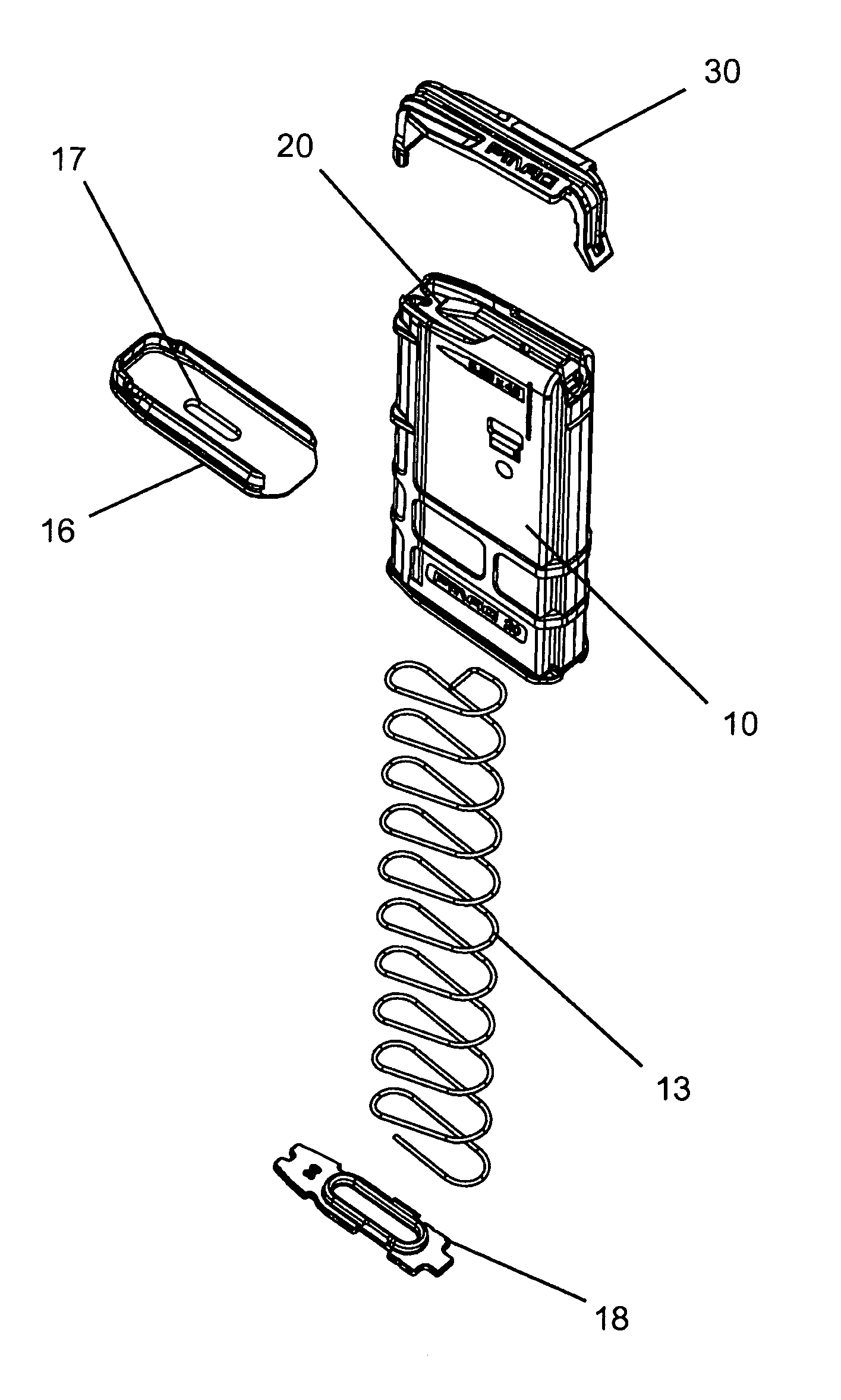
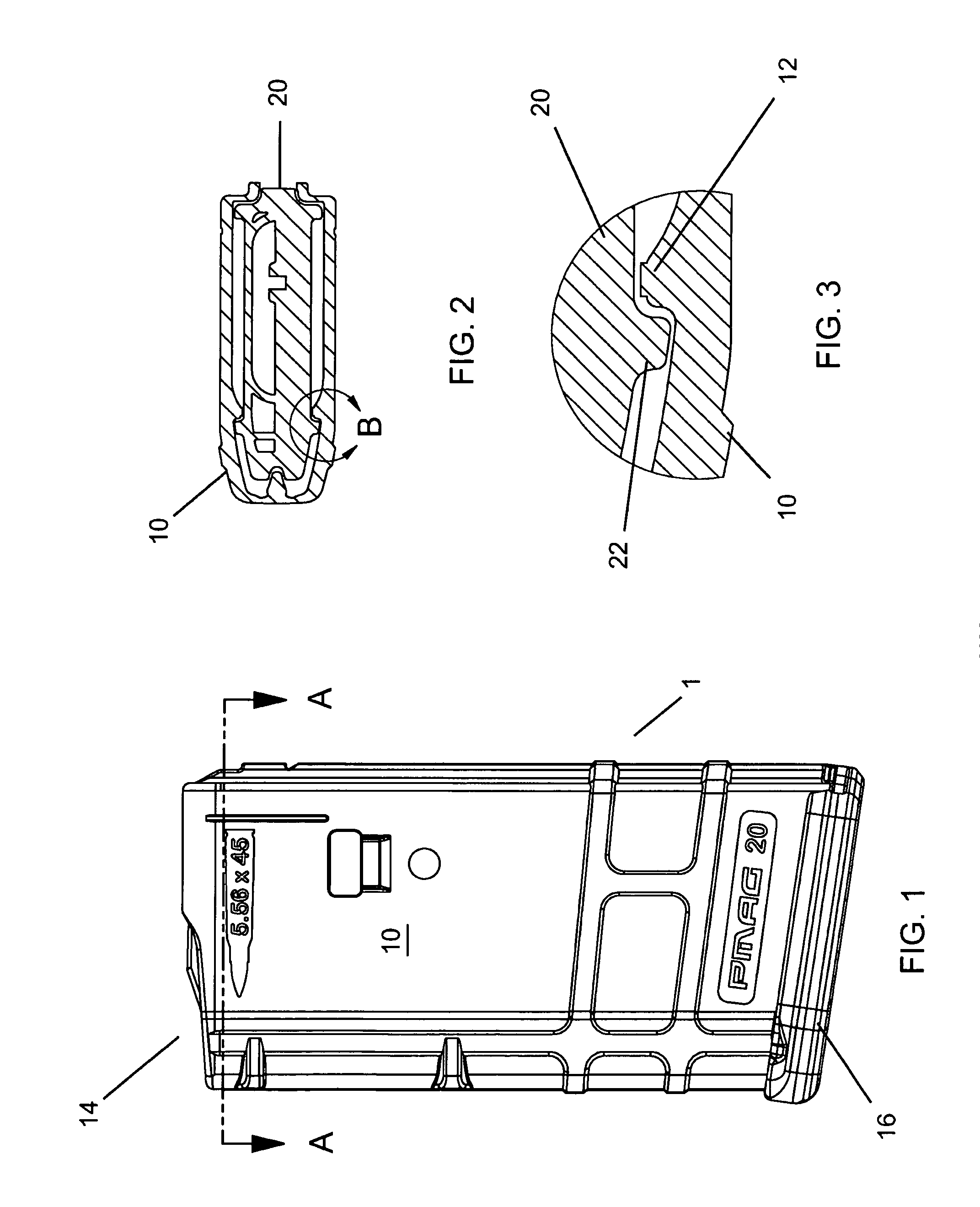
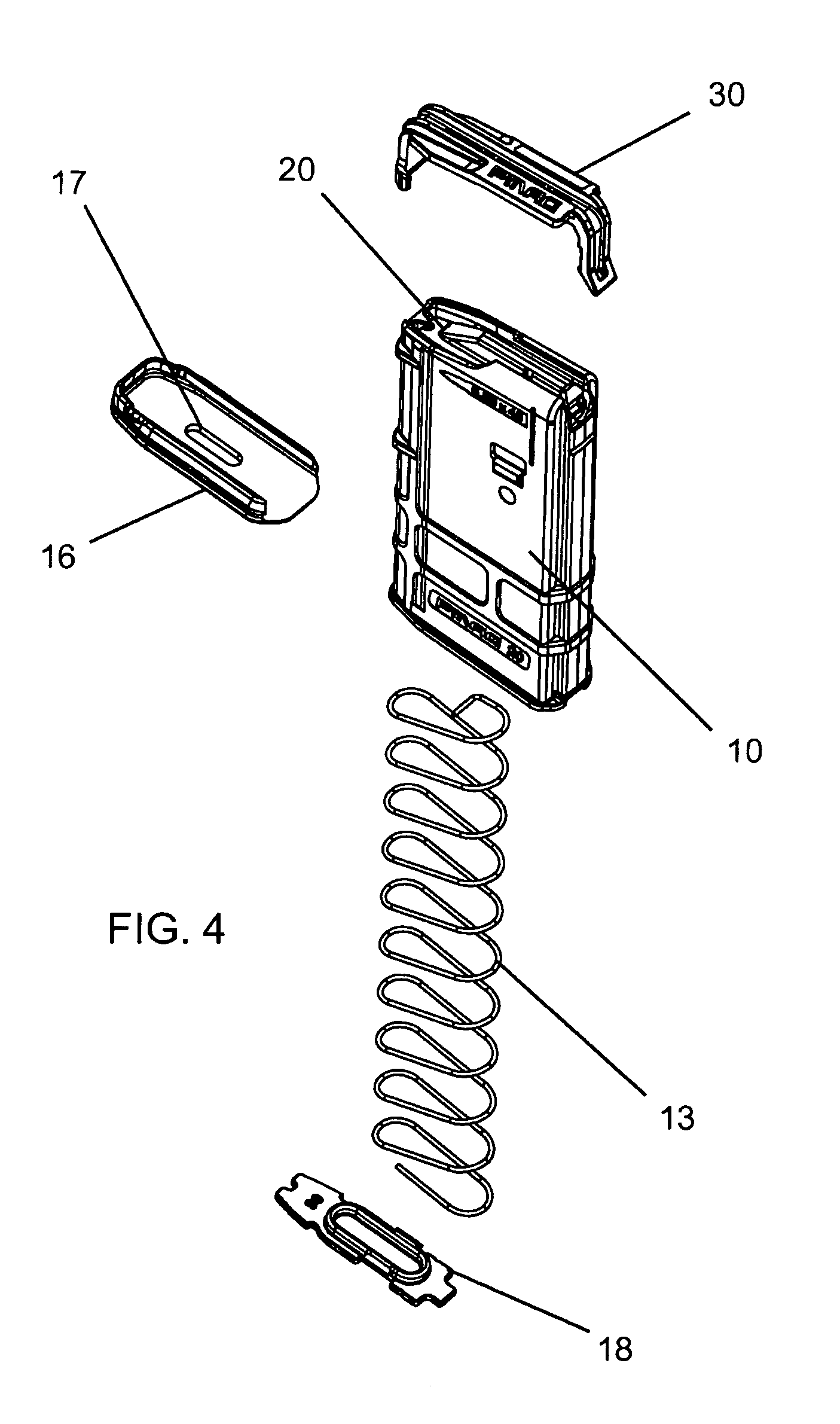
[0024]With reference to FIG. 1, the magazine 1 generally comprises a body 10 having a floor end (covered by floor plate 16) and a feed end 14. Feed lips 11 are provided at the feed end 14 to interface with a weapon and to guide cartridges into the firing chamber of said weapon. The floor end is capped with a floor plate 16 which is secured by a lock plate 18. As shown in FIGS. 6 and 8, a spring 13 rests against the lock plate 18, centered by walls on the lock plate 18, and floor plate 16 combination and provides tension to bias the follower 20 and the floor plate 16 so that the follower 20 will progress up the magazine body 10 as ammunition is used. Floor plate 16 slides over a rim of the floor end, using a ledge...


PUM


Abstract

The present invention is an ammunition magazine, preferably made of a glass fiber reinforced polymer, utilizing a structurally enhancing ridge, angular guide rails and a follower made to interface with said guide rails to reduce wobble. The preferred embodiment also features a protective cover that distributes forces from the spring to more structurally sound areas of the magazine, thus reducing feed end splay, and may include an ammunition indication system comprised of at least one window and a noticeable marker on the follower spring. The follower and magazine casing are also designed to interface to prevent the follower from popping out of the feed end and the floor plate of the magazine utilizes a locking plate and sliding relationship between the floor plate, locking plate and magazine to secure the floor plate onto the magazine casing.

Description

CROSS-REFERENCES TO RELATED APPLICATIONS[0001]This Application claims priority on earlier filed U.S. Provisional Application No. 60 / 941,646, filed on Jun. 1, 2007, and incorporates the same in its entirety by reference.FIELD OF THE INVENTION[0002]The present invention relates to the field of firearms and more particularly relates to an improved ammunition magazine.BACKGROUND OF THE INVENTION[0003]Ammunition magazines are well known in the art of firearms. Their basic construction is a containment shell with two open ends. One end is deemed the “floor” of the magazine and is covered by a plate while the opposite end is the “feed” end and interfaces with the weapon. Inside the volume defined by the shell and plate is a spring and follower assembly. When ammunition is loaded into the magazine, the ammunition pushes the follower down towards the floor and thereby compresses the spring. In use, when one magazine is expended, the compressed spring releases and pushes the follower and asso...

Claims


Application Information

Patent Timeline
Patent Type & Authority Applications(United States)
IPC IPC(8): F41A9/65F41A9/62
CPCF41A9/65
Inventor FITZPATRICK, RICHARD M.MAYBERRY, MICHAEL T.BURT, ERIC C.
Owner MAGPUL INDUSTRIES
Learn More