
Log supporting and guiding apparatus for improved burning

a technology of supporting apparatus and logs, which is applied in the direction of lighting and heating apparatus, grates, and stoves or ranges. it can solve the problems of less heat generated, insufficient airflow, and difficulty in burning wood in fireplaces, so as to maximize log burning, and the strength of the upper section. , to achieve the effect of maximizing the space for logs

Inactive Publication Date: 2011-01-06
KLEVE ROBERT B +1
View PDF12 Cites 6 Cited by
  • Summary
  • Abstract
  • Description
  • Claims
  • Application Information

AI Technical Summary

Benefits of technology

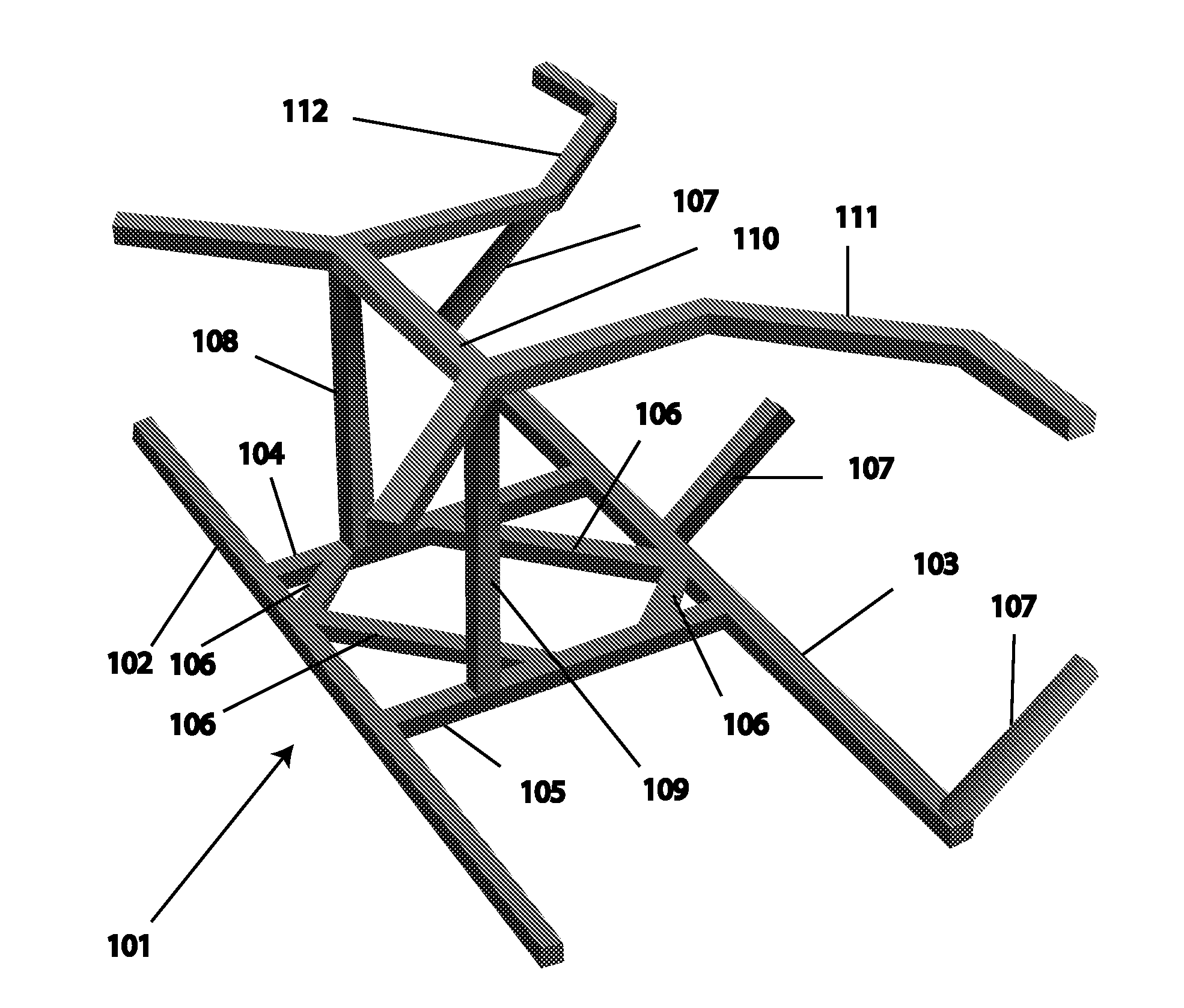
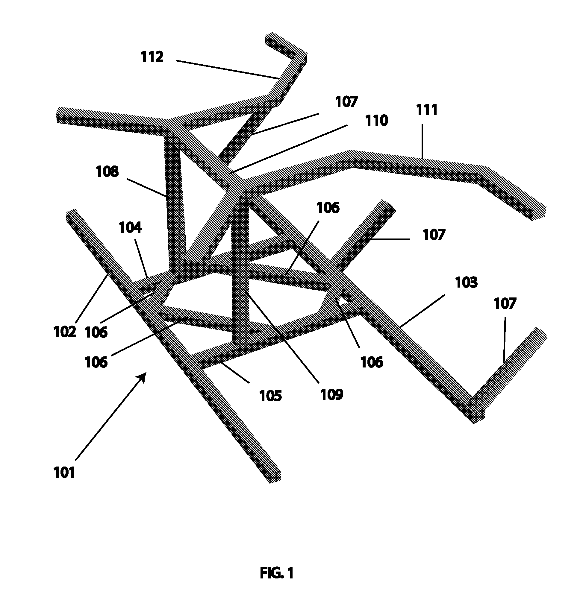
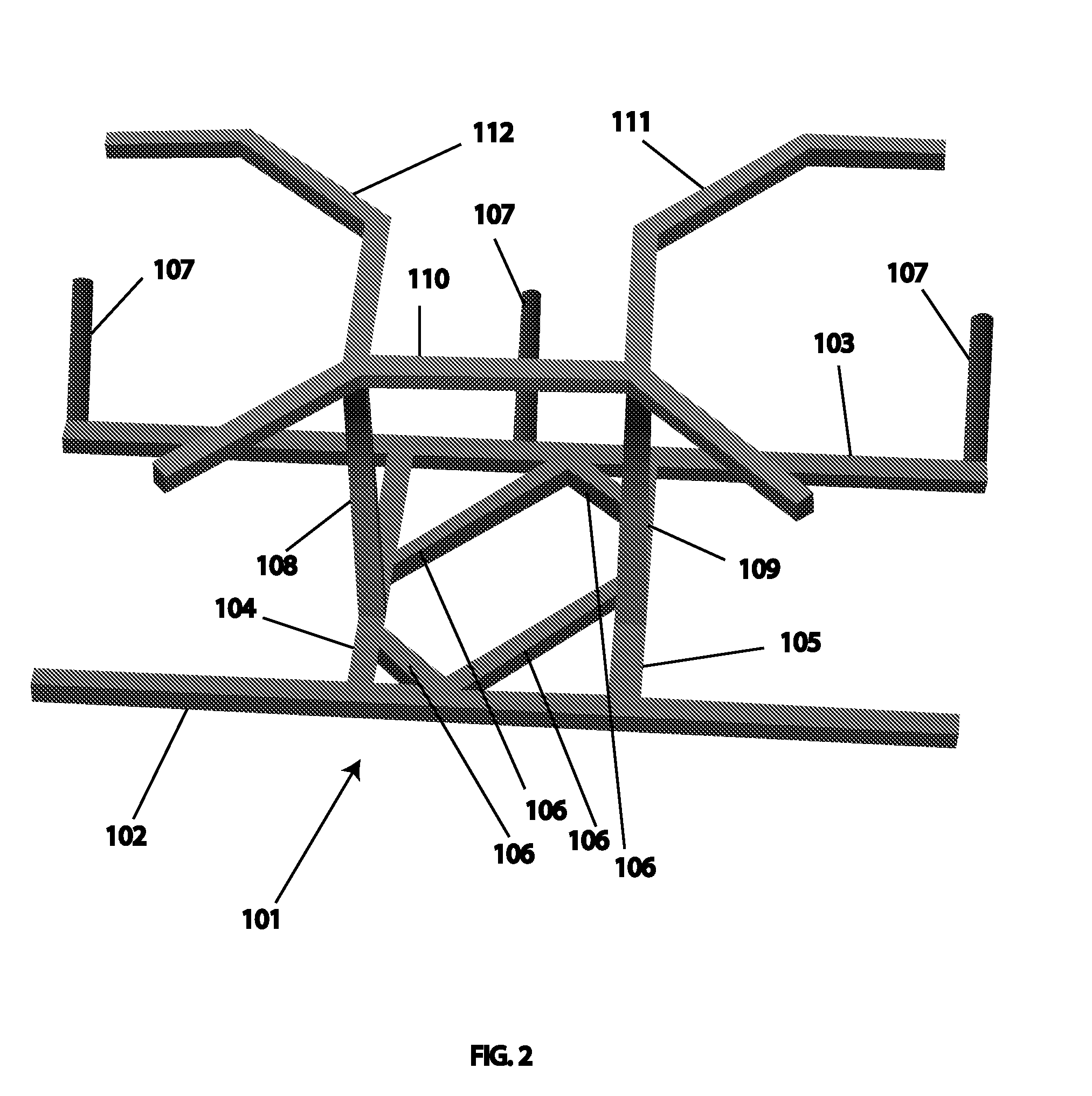
[0009]The base (without the strength reinforcing bars) typically resembles a ladder in shape, with the ladder-shaped base being placed flat on the fireplace. The base front bar and base back bar resemble the two legs of the ladder. The two connecting bars resemble steps of the ladder. The base rests in a stable manner on a fireplace grate or fireplace floor. The base provides the stability to support the other elements of the apparatus.
[0011]The upright bars enable the c-section bar and inverted c-section bar to be raised above the base of the apparatus, creating an upper section of the apparatus. The height of the upper section of the apparatus is high enough to enable additional logs to be placed in the center of the apparatus in a horizontal manner. The upright bars are vertical instead of angled, maximizing space for logs and log burning.
[0012]The cross bar reinforces the strength of the upper section of the apparatus while maximizing space for logs and log burning.

Problems solved by technology

Burning wood in a fireplace can be difficult under certain circumstances.
In particular, insufficient airflow can choke a fire.
This results in incomplete burning of the wood, smoke, and less heat generated.

Method used


Image

  • Log supporting and guiding apparatus for improved burning
  • Log supporting and guiding apparatus for improved burning
  • Log supporting and guiding apparatus for improved burning

Examples


Embodiment Construction

[0026]While prior art exists for improving fireplace airflow and wood burning, significant shortcomings exist. For example, U.S. Pat. No. 6,637,713 Kleve et al. has a tee-pee configuration where the top of the logs are too close together while the bottom of the logs are too far apart. This results in incomplete burning of the wood. Furthermore, the upper brackets of Kleve et al. are too small to accommodate larger log sizes.

[0027]The present disclosure describes a novel apparatus which overcomes the shortcomings of the prior art. Logs can be supported upright in four different positions and at varying angles to optimize burning. Furthermore, different sized and larger logs can be used because of the nature of the c-shaped and inverted c-shaped bar sections.

[0028]FIG. 1 shows an isometric view of an embodiment of the invention. The embodiment comprises; a base 101 which rests on a fireplace floor or fireplace grate and is comprised of a front bar 102, back bar 103, a left connecting ...


PUM


Abstract

A log supporting and guiding apparatus for improved burning, the apparatus comprising: a base which rests on a fireplace floor or fireplace grate, the base comprising a front bar, back bar, a left connecting bar, a right connecting bar, and a plurality of strength reinforcing bars; a plurality of log retaining bars which are functionally attached to the base and angled off of the fireplace floor or fireplace grate; a left upright bar which is perpendicular, functionally attached to the left connecting bar at the bottom of the left upright bar, and closer to the front bar than the back bar; a right upright bar which is perpendicular, functionally attached to the right connecting bar at the bottom of the right upright bar, and closer to the front bar than the back bar; a cross bar which functionally connects the top of the left upright bar with the top of the right upright bar; a c-section bar for holding a log upright, which is functionally attached to the top of the right upright bar; and an inverted c-section bar for holding a log upright, which is functionally attached to the top of the left upright bar.

Description

CROSS-REFERENCE TO RELATED APPLICATIONS[0001]This application claims the benefit of U.S. Provisional Application 61 / 222,228 filed Jul. 1, 2009. The content of this prior application is incorporated by reference in its entirety.FIELD OF THE INVENTION[0002]The present disclosure is in the technical field of log holding or supporting. More particularly, the present disclosure relates to a log supporting apparatus for supporting logs and the like in a fireplace for burning.BACKGROUND OF THE INVENTION[0003]Burning wood in a fireplace can be difficult under certain circumstances. In particular, insufficient airflow can choke a fire. This results in incomplete burning of the wood, smoke, and less heat generated.[0004]U.S. Pat. No. 6,637,713 Kleve et al. describes a triangular teepee-shaped apparatus for supporting logs in a fireplace. Kleve et al. discusses the need for supporting logs in a partly upright position inclined toward one another in a fireplace for easier or better burning of t...

Claims


Application Information

Patent Timeline
IPC IPC(8): F24B1/193
CPCF24B1/193
Inventor KLEVE, ROBERT B.JONES, MARK D.
Owner KLEVE ROBERT B
Learn More