Method for activating a superimposed steering system

Inactive Publication Date: 2010-12-30
ZF LENKSYST
View PDF8 Cites 8 Cited by
  • Summary
  • Abstract
  • Description
  • Claims
  • Application Information

AI Technical Summary

Benefits of technology

[0013]Changing the time delay, or varying the magnitude of the time delay, allows the driving speed to be included in the calculation of the steering ratio, and therefore in the motor target angle, as quickly as possible, particularly in situations in which the vehicle decelerates quickly, so that no movement is generated in the steering wheel when the vehicle has come to a stop.

Problems solved by technology

If the vehicle decelerates quickly with the steering wheel turned, the time delay produced by the signal filter may result in a movement of the steering wheel after the vehicle has come to a stop.
This movement is undesired.

Method used


Image

  • Method for activating a superimposed steering system
  • Method for activating a superimposed steering system
  • Method for activating a superimposed steering system

Examples


Embodiment Construction

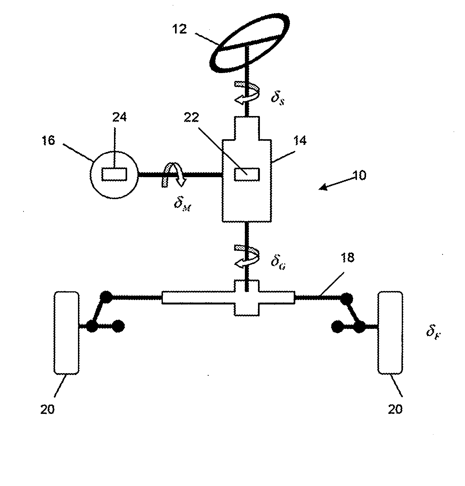
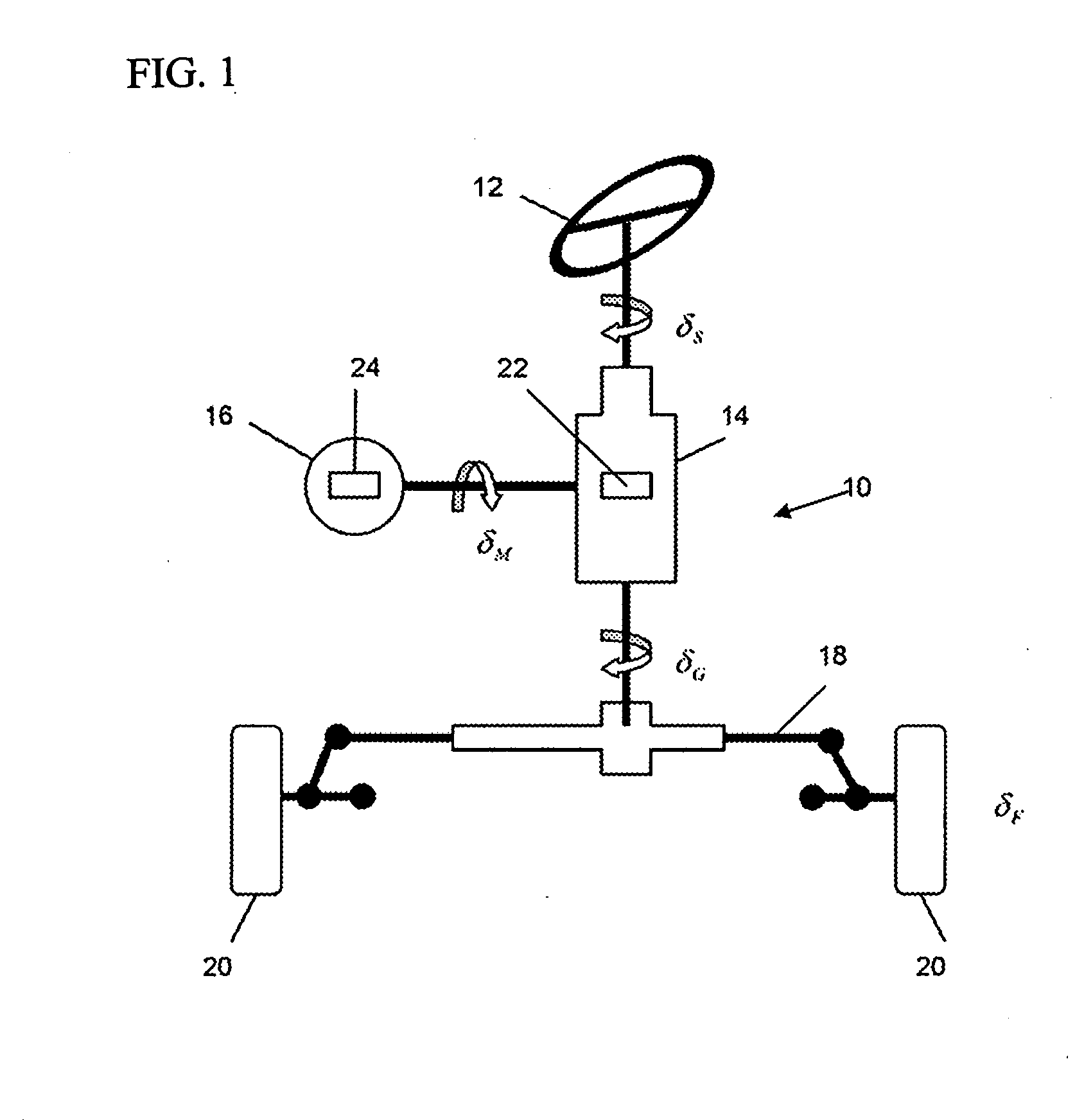
[0028]FIG. 1 illustrates an embodiment of the superimposed steering system according to the invention, indicated in its entirety by reference numeral 10. The illustration shows: a steering handle 12, which in this case is a steering wheel; a steering transmission 14; an additional angle actuator 16; and two front wheels 20, which are connected by way of a front axle 18 and coupled so as to allow the vehicle to be controlled.

[0029]Furthermore, a controller 22 is provided for actuating an electric motor 24 of the additional angle actuator 16.

[0030]In the steering transmission 14, the steering angle δS specified by way of the steering handle 12 is superimposed with an additional angle, or motor steering angle δM, which is the superimposed additional angle of the electric motor 24, of the additional angle actuator 16, resulting in a pinion angle δG which directly influences the steering angles δF at the front wheels.

[0031]The following applies

iv=δSδF

[0032]and

δM×iM+δS×iD=δG

[0033]where i...


PUM


Abstract

Disclosed is a method for actuating a superimposed steering system, a superimposed steering system, a controller, a computer program, and a computer program product. In the method, a steering ratio is produced as a function of the driving speed, with the magnitude of a time delay being adjusted as a function of the driving speed.

Description

REFERENCE TO RELATED APPLICATION[0001]This is a continuation application of PCT / EP2008 / 059344, filed Jul. 17, 2008. The subject matter of the aforementioned prior applications is hereby incorporated herein by reference.BACKGROUND OF THE INVENTION[0002]The invention relates to a method for operating a superimposed steering system, to such a superimposed steering system, to a controller for use in such a superimposed steering system, and to a computer program and a computer program product having program code means for carrying out such a method.[0003]In a superimposed, or angular superimposed steering system, the steering wheel angle specified by the driver is superimposed with a superimposition angle, or additional angle, in order to provide situation-dependent support for the driver. This produces what is referred to as the pinion angle, which determines the actual steering angle, and thus the degree of excursion of the coupled wheels.[0004]The speed-dependent variable transmission...

Claims


Application Information

Patent Timeline
IPC IPC(8): B62D6/00
CPCB62D5/008B62D6/02B62D6/002
Inventor BUERING, HENDRIKGROSSHEIM, REINHARDWANNER, THOMAS
Owner ZF LENKSYST
Why Eureka
Try Eureka