
Method and apparatus for compensating for transceiver impairments

Active Publication Date: 2010-12-30
ALCATEL LUCENT SAS
View PDF4 Cites 17 Cited by
  • Summary
  • Abstract
  • Description
  • Claims
  • Application Information

AI Technical Summary

Problems solved by technology

This compensation is difficult because it is necessary to calibrate the direct conversion transmitter and direct conversion receiver individually using a separate external reference for each path.
If an uncompensated receiver is used to calibrate a transmitter over the complete frequency span, the transmitter calibration will be corrupted by the impairments of the receiver, and vice versa.

Method used


Image

  • Method and apparatus for compensating for transceiver impairments
  • Method and apparatus for compensating for transceiver impairments
  • Method and apparatus for compensating for transceiver impairments

Examples


Embodiment Construction

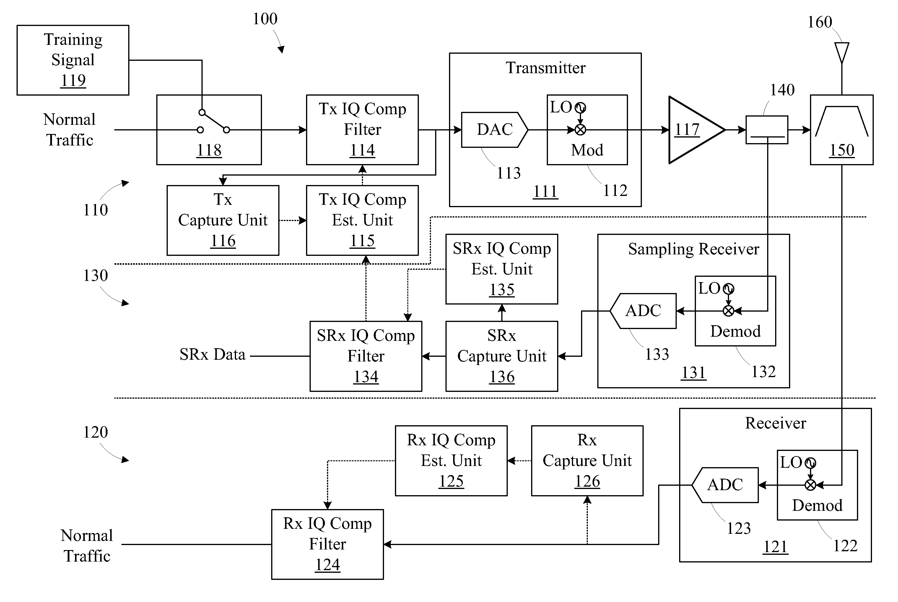
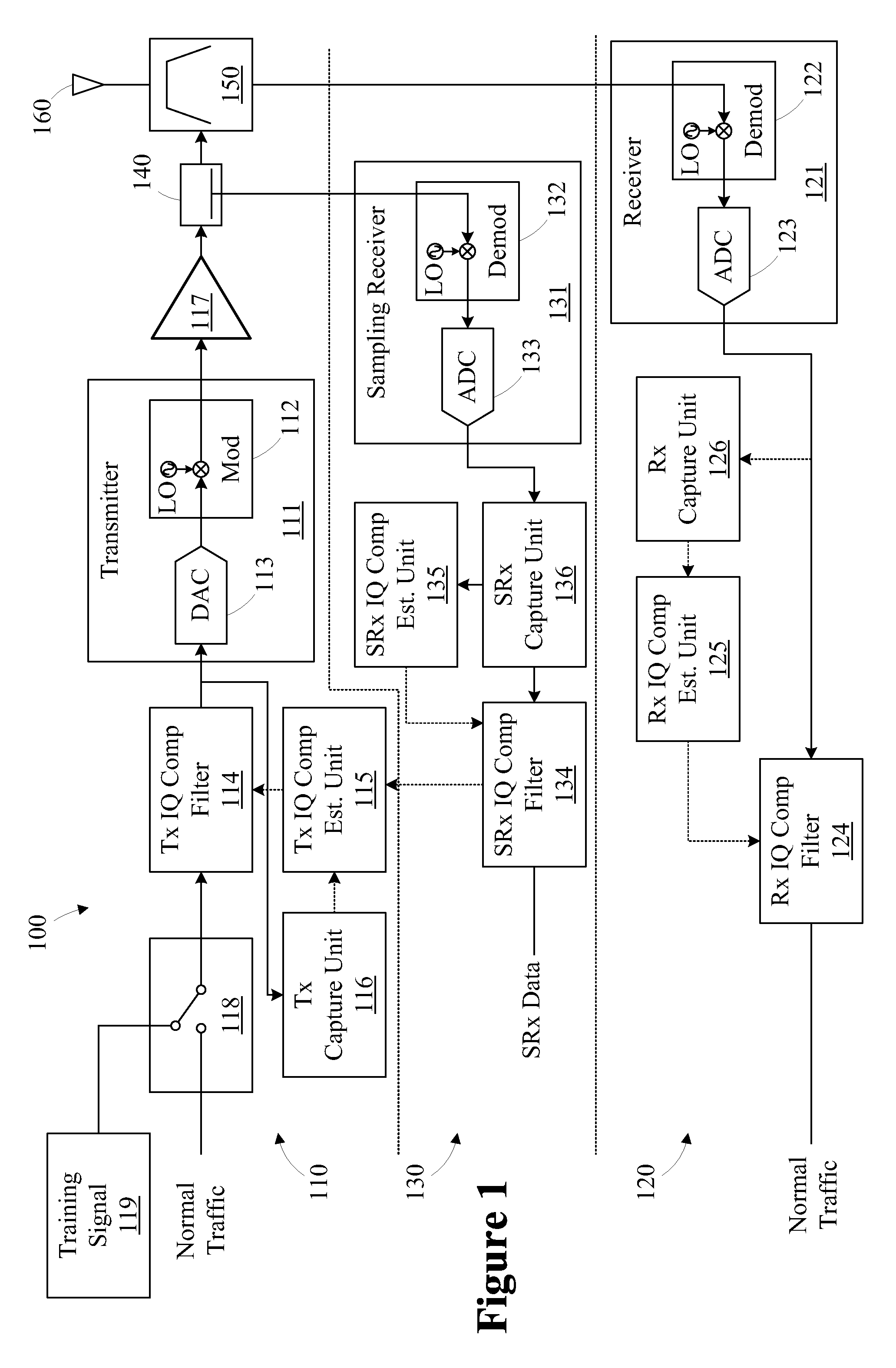
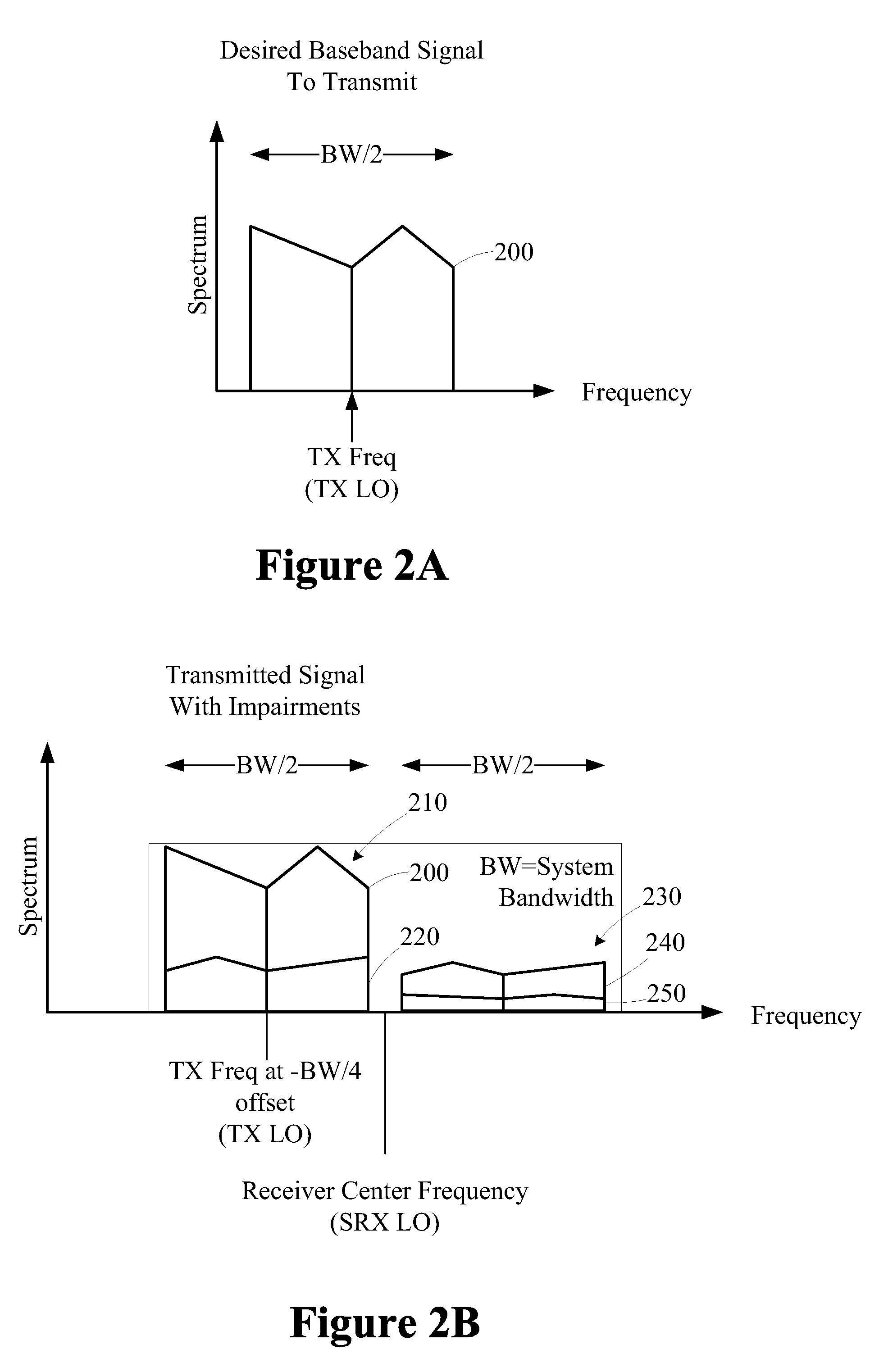
[0016]One or more specific embodiments of the disclosed subject matter will be described below. It is specifically intended that the disclosed subject matter not be limited to the embodiments and illustrations contained herein, but include modified forms of those embodiments including portions of the embodiments and combinations of elements of different embodiments as come within the scope of the following claims. It should be appreciated that in the development of any such actual implementation, as in any engineering or design project, numerous implementation-specific decisions must be made to achieve the developers' specific goals, such as compliance with system-related and business related constraints, which may vary from one implementation to another. Moreover, it should be appreciated that such a development effort might be complex and time consuming, but would nevertheless be a routine undertaking of design, fabrication, and manufacture for those of ordinary skill having the b...


PUM


Abstract

A method for compensating a transceiver for impairments includes transmitting a plurality of partial bandwidth training signals using a transmitter. A plurality of response signals of a receiver having a bandwidth and exhibiting receiver impairments is captured. Each response signal is associated with one of the partial bandwidth training signals. Each of the partial bandwidth training signals is associated with a portion of the receiver bandwidth. A plurality of partial compensation filters is generated based on the plurality of response signals. Each partial compensation filter is associated with one of the response signals. The partial compensation filters are combined to configure a receiver compensation filter operable to compensate for the receiver impairments.

Description

CROSS-REFERENCE TO RELATED APPLICATIONS[0001]Not applicable.BACKGROUND[0002]The disclosed subject matter relates generally to telecommunication and, more particularly, to a method and apparatus for compensating for transceiver impairments.[0003]In telecommunication, direct-conversion techniques involve mixing a baseband signal with a carrier signal without using an intermediate frequency. A direct conversion receiver (DCR), also known as homodyne, synchrodyne, or zero-IF receiver, may then demodulate incoming signals by mixing the incoming signal with a local oscillator signal synchronized in frequency to the carrier signal. The baseband signal may then be obtained simply by low-pass filtering the mixer output, without requiring further detection.[0004]A direct conversion transceiver may be implemented on a single chip, making it inexpensive and versatile. However, the transmission and receive paths for the base band signals (i.e., in-phase (I) and quadrature (Q)) are independently ...

Claims


Application Information

Patent Timeline
IPC IPC(8): H04B1/38
CPCH04B1/30H04L27/34H04B1/62
Inventor HEUTMAKER, MICHAEL STEVENHONCHARENKO, WALTER
Owner ALCATEL LUCENT SAS
Learn More