
Clamp for single-handed operation

a single-handed operation and clamping technology, applied in the direction of fastening means, drawing boards, printing, etc., can solve the problems of not always convenient or a viable option, objects may fall out of the clamping, and two hands are not available for placing objects

Active Publication Date: 2010-12-30
INTUITIVE RES TECH
View PDF68 Cites 23 Cited by
  • Summary
  • Abstract
  • Description
  • Claims
  • Application Information

AI Technical Summary

Benefits of technology

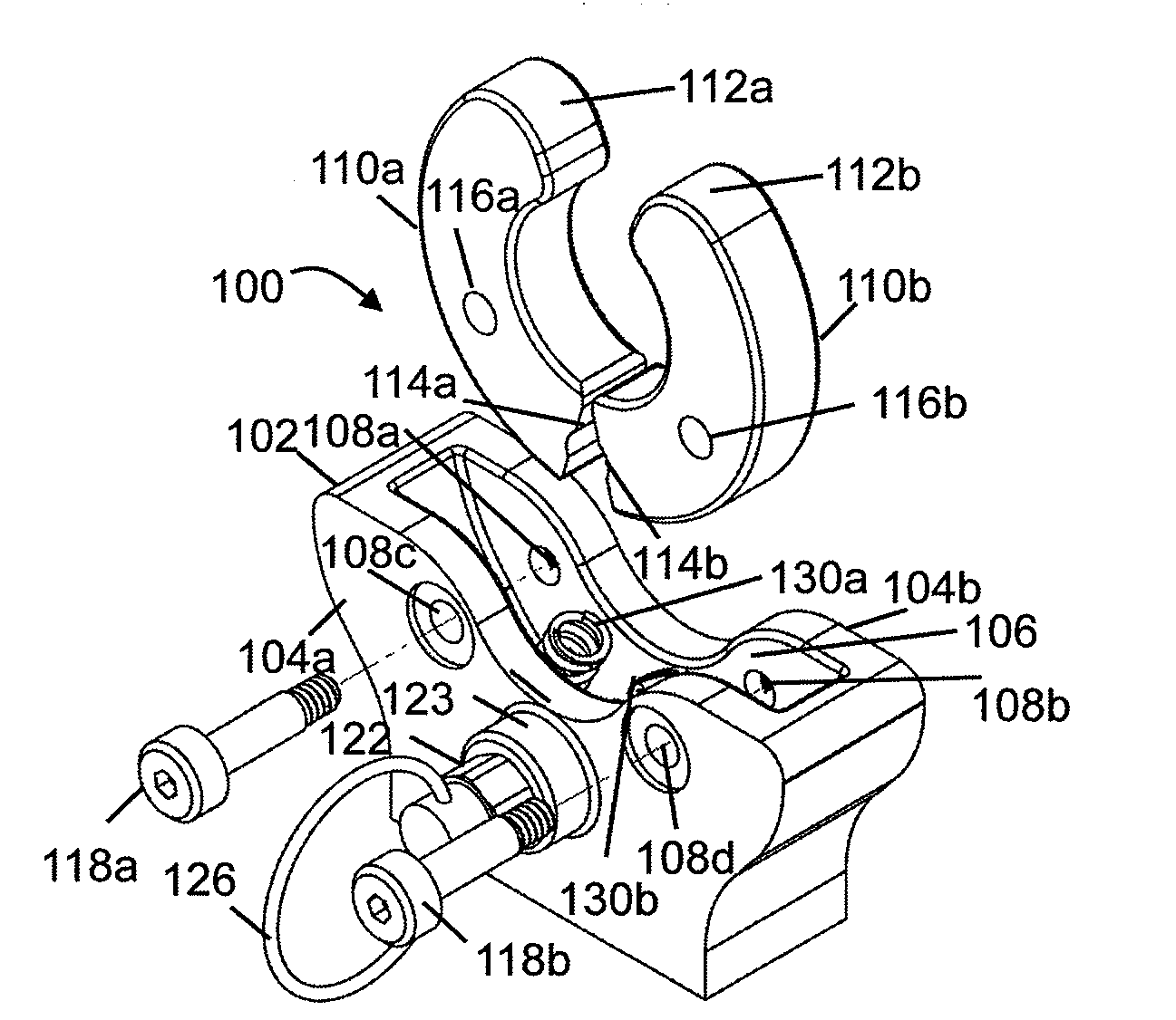
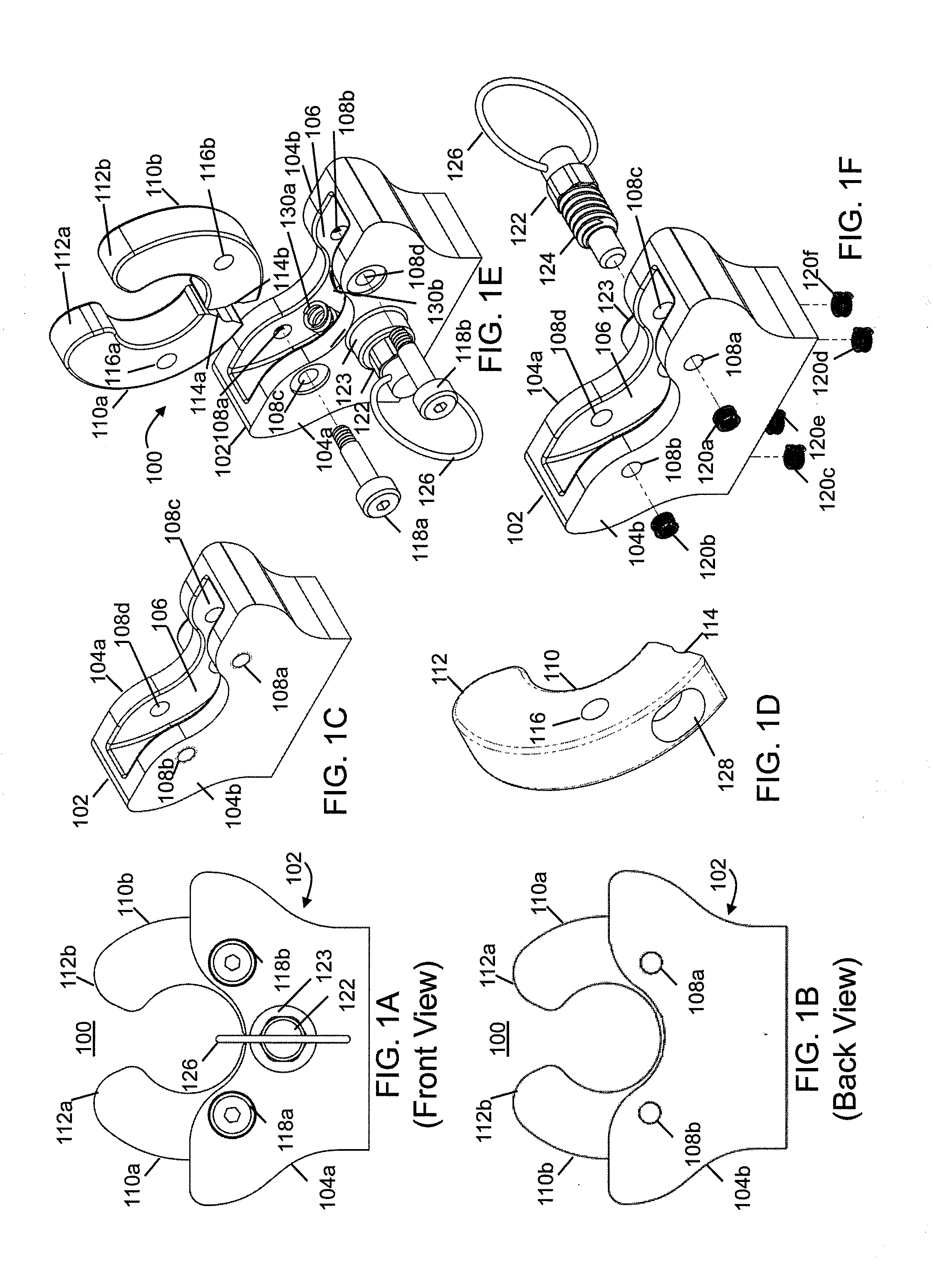
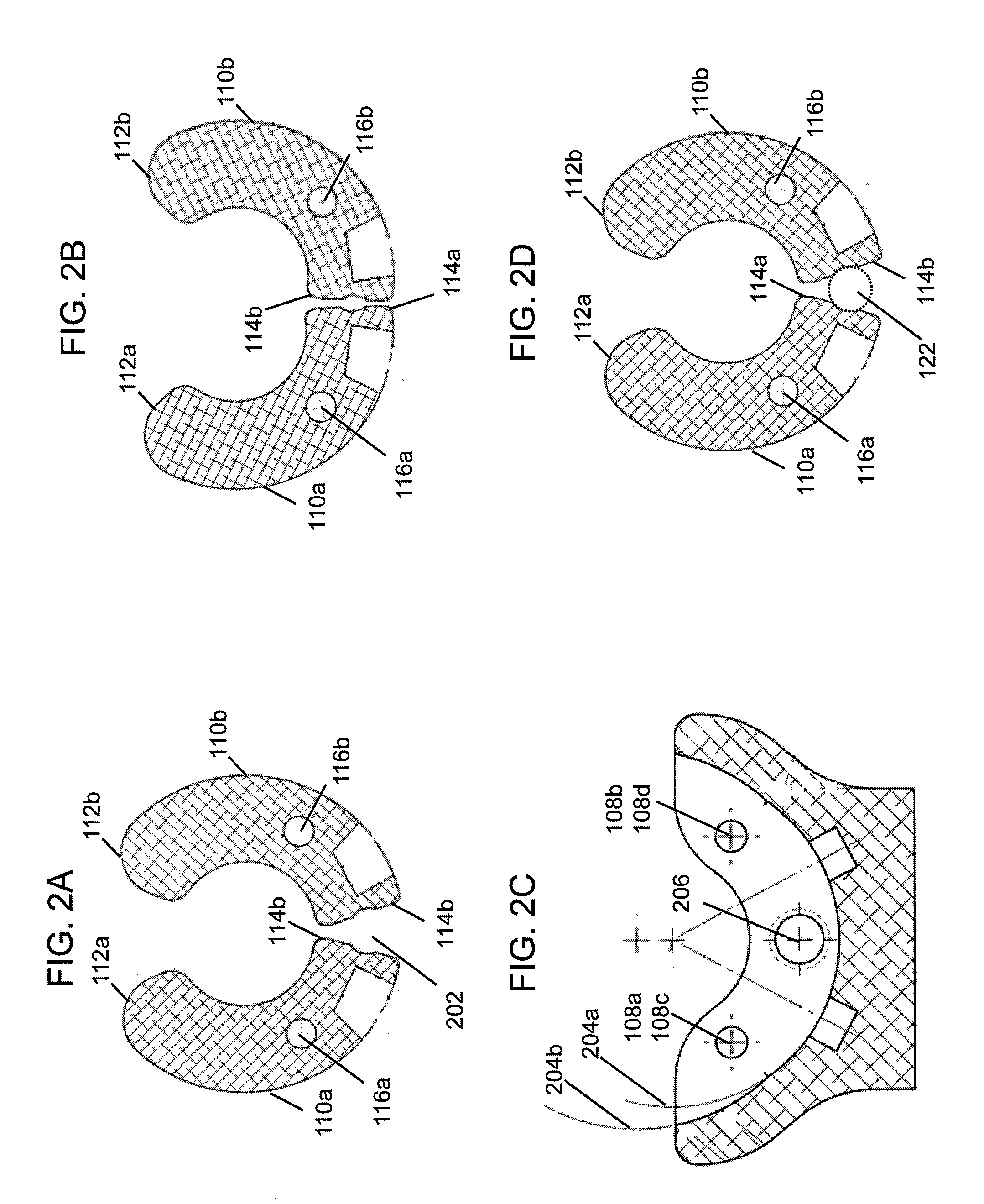
[0006]Briefly, according to the present invention, a clamp has an open state for inserting an object from a front end and a closed state for holding the inserted object relative to a back end. The clamp includes a frame as well as a first arm and a second arm that are positioned within the frame. At least one of the first or second arms is pivotable relative to the other along a range of motion that traverses an open position corresponding to the open state of the clamp and a closed position corresponding to the closed state of the clamp...

Problems solved by technology

Most conventional clamps require a person to have both hands available to secure an object within the clamp or to open the clamp to release the object, which is not always convenient or a viable option at the time of use.
Similarly, while the clamp is being opened by one hand that same hand is not able to hold onto the object, so that object may fall out of the clamp.
But, in certain applications, two hands are not available for placing an object into or removing an object from a clamp.
Conventional clamps that do allow single-handed operation, such as various types of clamps used to hold handles of brooms, mops, and of various types of tools, typically do not have a means for locking the clamp in its closed clamp state and do not perform well in overhead applications where the weight of an object placed into such a clamp can cause it to fall out of the clamp, in particular in an application where another object to which the clamp is attached is jarred suddenly.
For example, such conventional clamps for single-handed operation would not be desirable in an application where a heavy object needs to be attached to the roof of a vehicle traveling across rough terrain or secured within a spacecraft.

Method used


Image

  • Clamp for single-handed operation
  • Clamp for single-handed operation
  • Clamp for single-handed operation

Examples


Embodiment Construction

[0034]The present invention will now be described more fully in detail with reference to the accompanying drawings, in which the preferred embodiments of the invention are shown. This invention should not, however, be construed as limited to the embodiments set forth herein; rather, they are provided so that this disclosure will be thorough and complete and will fully convey the scope of the invention to those skilled in the art. Like numbers refer to like elements throughout.

[0035]The present invention provides a clamp for single-handed operation. The invention allows a person to place an object into the clamp with one hand. The clamp will transition from a closed clamp state to an open clamp state when an object is pressed against the outside of the clamp. The object will then continue into the clamp while the clamp is in its open clamp state. Once inside the clamp, the object will engage the back of the inside of the clamp thereby causing the clamp to transition from the open cla...


PUM


Abstract

A clamp has an open state for inserting an object from a front end and a closed state for holding the inserted object relative to a back end. The clamp includes a frame as well as a first arm and a second arm that is positioned within the frame. At least one of the first or second arms is pivotable relative to the other along a range of motion that traverses an open position corresponding to the open state of the clamp and a closed position corresponding to the closed state of the clamp. In one embodiment, at least one of the first and second arms are shaped to position the object between a front end and a back end when the clamp is in the closed state such that a pressure exerted by insertion of the object to the backend causes the front end to move along the range of motion to the closed position. A locking mechanism locks the clamp to the closed state when the front end reaches the closed position and unlocks the clamp to the open state by allowing the front end to move along the range of motion to reach the open position.

Description

FIELD OF THE INVENTION [0001]The present invention relates generally to a clamp for single-handed operation. More particularly, the present invention relates to single-handed operation for both closing and opening while still constraining the object after release to prevent accidental fallout.BACKGROUND OF THE INVENTION [0002]Most conventional clamps require a person to have both hands available to secure an object within the clamp or to open the clamp to release the object, which is not always convenient or a viable option at the time of use. More specifically, conventional clamp mechanisms typically require a person to use one hand to open or close the clamp while the other hand is needed to hold or otherwise control the object being placed into the clamp or being removed from the clamp. If only one hand is available to secure the object within the clamp, the object may fall out of the clamp after it has been placed into the clamp with one hand when that same hand must release the...

Claims


Application Information

Patent Timeline
IPC IPC(8): B25B5/04B25B5/06B25B5/16
CPCB25B5/04B25B5/06B25B5/14F16B2/10B25B5/16B25B5/163B25B5/147
Inventor CLARK, JEREMY TRENTSHELTON, VERGENIA CHANTEL
Owner INTUITIVE RES TECH
Learn More