
Sealed bearing

Inactive Publication Date: 2010-12-23
COMML DE UTILES Y MOLDES
View PDF6 Cites 3 Cited by
  • Summary
  • Abstract
  • Description
  • Claims
  • Application Information

AI Technical Summary

Benefits of technology

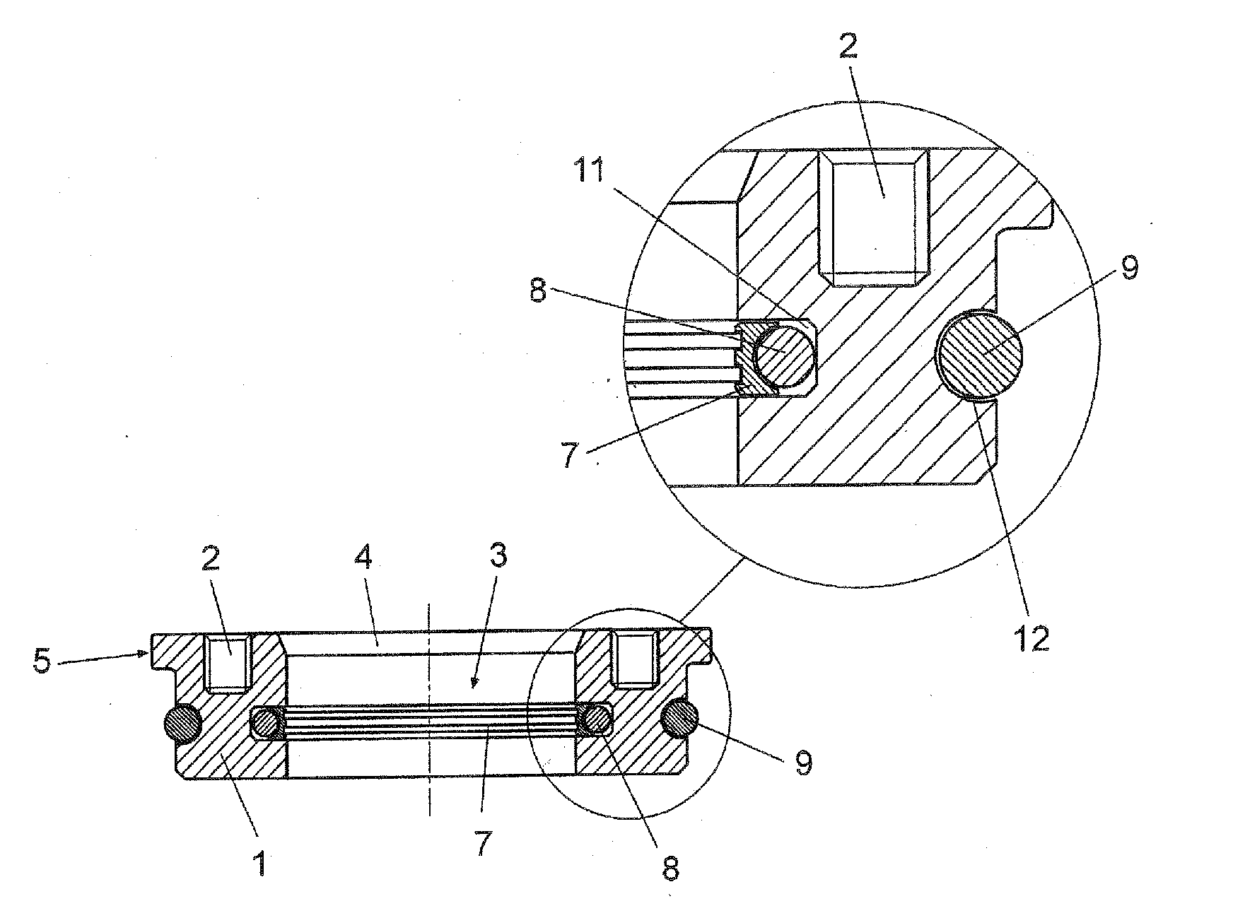
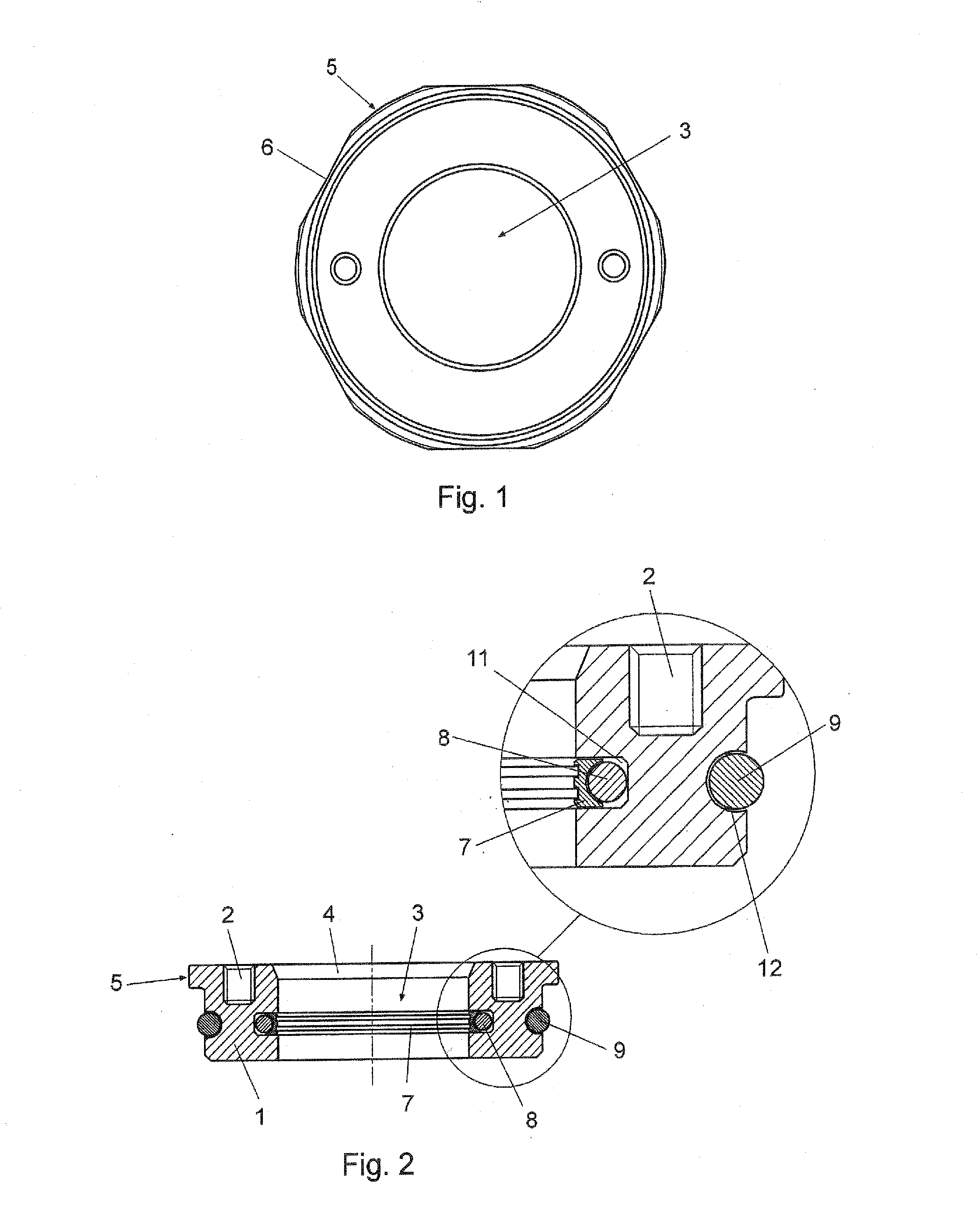
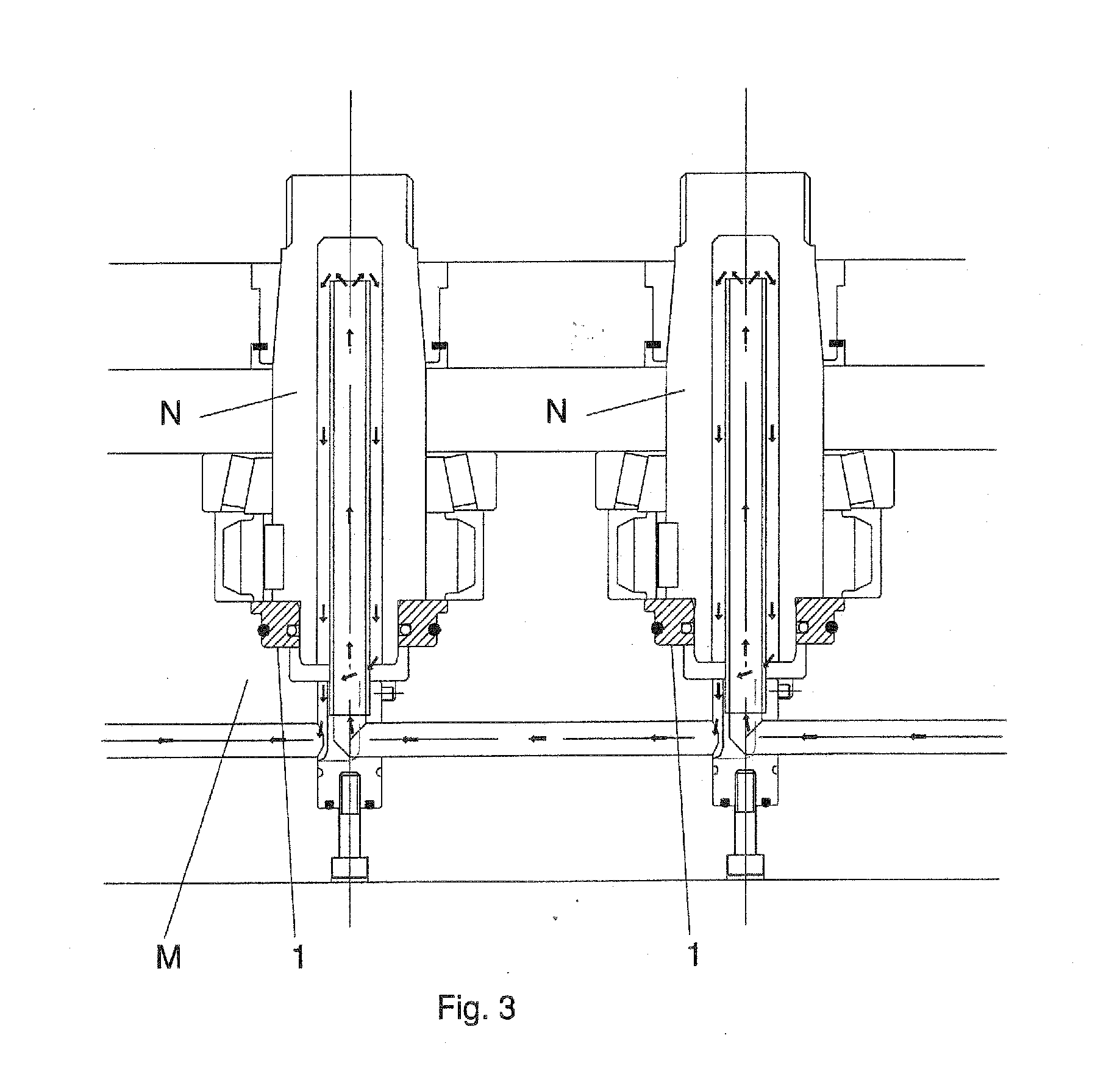
[0010]The sealed bearing object of the invention has particularities aimed at providing it with a dual functionality, as a bearing and as a rotary seal simultaneously, at allowing the accumulation of pressure in the cooling channels of the internally cooled core pins or shafts, therefore allowing the series connection thereof in the mold or support part, considerably reducing the space necessary for the implementation of the assembly in the mold or support part and reducing to one the bearings necessary for the correct guiding of the rotating shaft or core pin.
[0015]The mentioned dual-effect rotary seal with high wear resistance, activated by a first O-ring seal, provides low friction and minimizes abrupt movement, being inserted in a main body defined as a support of the shaft which stabilizes the rotation of the shaft or core pin inside the bearing body, guiding and balancing said rotation.
[0017]The invention thus has the advantage of perfectly guiding the shaft in rotational movement, making it unnecessary to implement a second bearing or ball bearing, necessarily used in current applications.
[0021]The bearing body is provided at the upper part with threaded holes for facilitating its grip and extraction from the housing of the mold or support part.

Problems solved by technology

In the first case, although they allow the cooling of the rotating shaft or core pin, they do not allow accumulating pressure inside the cooling channels of the shaft or core pin, which makes their connection in series with the successive rotary shafts or core pins impossible.
This forces the constructing workshop to make individualized cooling channels for each shaft or core pin in the mold or support part, with the consequent constructive complexity due to the space that this requires, and the increase in manufacturing costs; in the second case, although it allows accumulating pressure inside the cooling channels, it must be connected individually by means of flexible tubes outside the mold, also considerably increasing the dimensions of the mold.
Another drawback of the mentioned rotary elements is that they are mechanical closures, not balanced by any internal mechanism, the use of the mentioned bearings or ball bearings for the correct assembly of the rotary shaft or core pin in the mold or support part being inevitable.

Method used


Image

  • Sealed bearing
  • Sealed bearing
  • Sealed bearing

Examples


Embodiment Construction

[0010]The sealed bearing object of the invention has particularities aimed at providing it with a dual functionality, as a bearing and as a rotary seal simultaneously, at allowing the accumulation of pressure in the cooling channels of the internally cooled core pins or shafts, therefore allowing the series connection thereof in the mold or support part, considerably reducing the space necessary for the implementation of the assembly in the mold or support part and reducing to one the bearings necessary for the correct guiding of the rotating shaft or core pin.

[0011]Another objective of the invention is to provide a balancing to the rotating shaft or core pin and to provide the correct and optimized assembly of a rotary seal design of those existing on the market which allows an operation with pressure, necessary to be able to connect in series an undetermined number of core pins or shafts to a cooling channel.

[0012]The sealed bearing object of the invention is of the type of those ...


PUM


Abstract

The invention relates to a sealed bearing which comprises a body with a general cylindrical configuration for its assembly in the housing of a mold or support body, and has a cylindrical inner hole for the assembly and balancing of the tight movement of a rotary shaft or core pin provided with internal cooling. The body has: an inner channel for the assembly of a dual-effect rotary seal activated by a first O-ring seal; an outer channel for the assembly of a second O-ring seal for the static sealing of the bearing in the housing of a mold or support part; and, at one of its ends, a head with peripheral planes and threaded holes for its grip and extraction from the housing of the mold or support part.

Description

CROSS-REFERENCE TO RELATED APPLICATIONS[0001]The present application claims the benefit under 35 U.S.C. 119(a)-(d) of Spanish Patent Application No. P200930330, filed on Jun. 18, 2009, the entire contents of which are incorporated herein by reference.OBJECT OF THE INVENTION[0002]The present invention relates to a sealed bearing acting simultaneously as a bearing and as a rotary seal.[0003]This sealed bearing is applicable in the rotary shafts, cores or core pins provided with internal cooling; especially in the core pins of injection molds with automatic unscrewing systems and generally in any rotating core pin, core or shaft with internal cooling.BACKGROUND OF THE INVENTION[0004]In different fields of the industry, among others in the field of injection molds, rotary shafts or core pins provided with internal cooling have been used.[0005]In these cases the shafts or core pins require at least two bearings or ball bearings for their correct assembly and alignment on the correspondin...

Claims


Application Information

Patent Timeline
IPC IPC(8): F16C33/74
CPCF16J15/3208F16C17/10F16C33/74
Inventor NAVARRA PRUNA, ALBERTO
Owner COMML DE UTILES Y MOLDES
Learn More