
Vehicle Light

Inactive Publication Date: 2010-12-23
STANLEY ELECTRIC CO LTD
View PDF6 Cites 6 Cited by
  • Summary
  • Abstract
  • Description
  • Claims
  • Application Information

AI Technical Summary

Benefits of technology

[0006]The presently disclosed subject matter was devised in view of these and other problems and features and in association with the conventional art. According to an aspect of the presently disclosed subject matter, a light (or a vehicle light) can prevent the generation of glar

Problems solved by technology

In addition, the reflected light cannot be directed to the light projection direction

Method used


Image

  • Vehicle Light
  • Vehicle Light
  • Vehicle Light

Examples


Embodiment Construction

[0019]A description will now be made below to lights, and more particularly to vehicle lights, of the presently disclosed subject matter with reference to the accompanying drawings in accordance with exemplary embodiments.

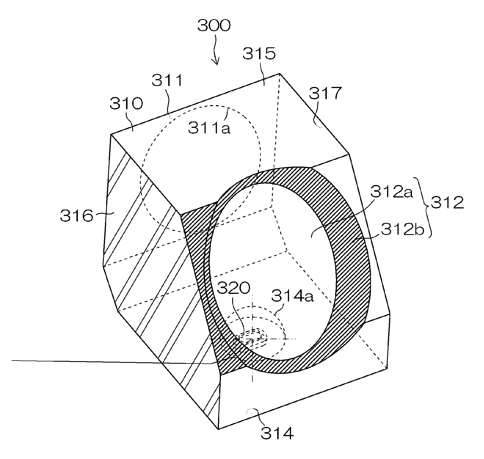
[0020]A vehicle light 300 of the exemplary embodiment as shown in FIG. 3 can be utilized as a vehicle headlight (for example, a headlamp, a signal lamp and the like for use in automobiles, motorcycles and the like). As shown in FIG. 3, the vehicle light 300 of FIG. 3 can include a lens body 310 made of a transparent resin, a light source 320, and the like.

[0021]The lens body 310 can be molded by injection molding a transparent resin such as acrylic resin, polycarbonate resin or the like into a solid lens body. FIG. 3 is a perspective view when the lens body 310 is viewed from its rear, left upper side while the light projection side is defined as a front surface. The lens body 310 can include a front surface 311 that is positioned in the front side of a vehicle bod...


PUM


Abstract

A vehicle light can prevent the generation of glare light due to the reflection of light from a connecting surface surrounding a reflecting surface when a lens body including the reflecting surface and the connecting surface surrounding the reflecting surface is used and light emitted from an LED light source enters the lens body. The vehicle light can include a light source and a lens body. The lens body can include optical surfaces including the reflecting surface configured to form a predetermined light distribution pattern, and connecting surfaces that shape and define a structure of the lens body by connecting the optical surfaces, but that do not engage in the formation of the light distribution pattern. The connecting surface surrounding the reflecting surface can reflect part of incident light from the light source to a direction that is different from the direction by the reflecting surface and is directed to any one of connecting surfaces. One of the connecting surfaces can receive the light reflected by the connecting surface and project the light therethrough.

Description

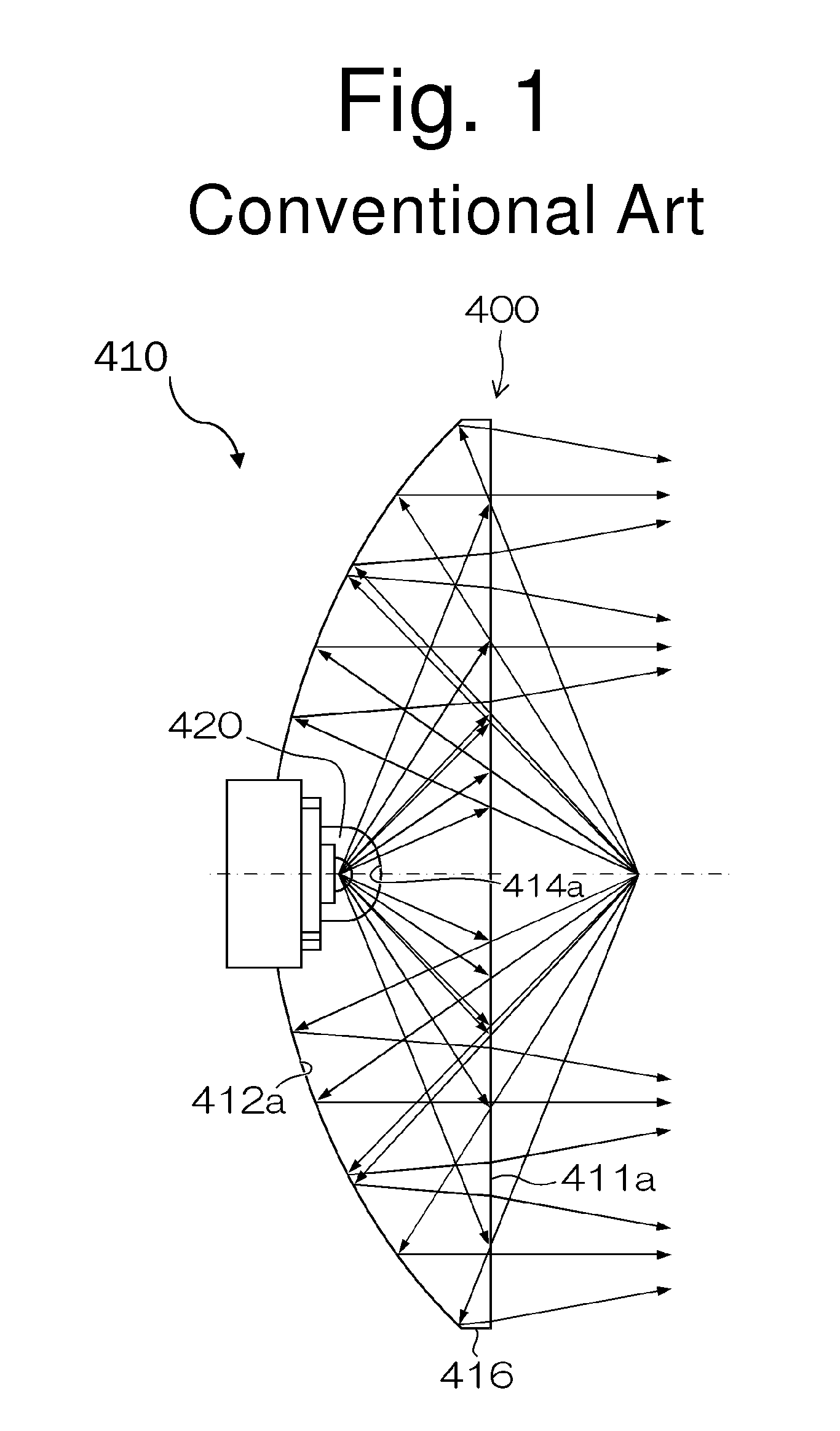
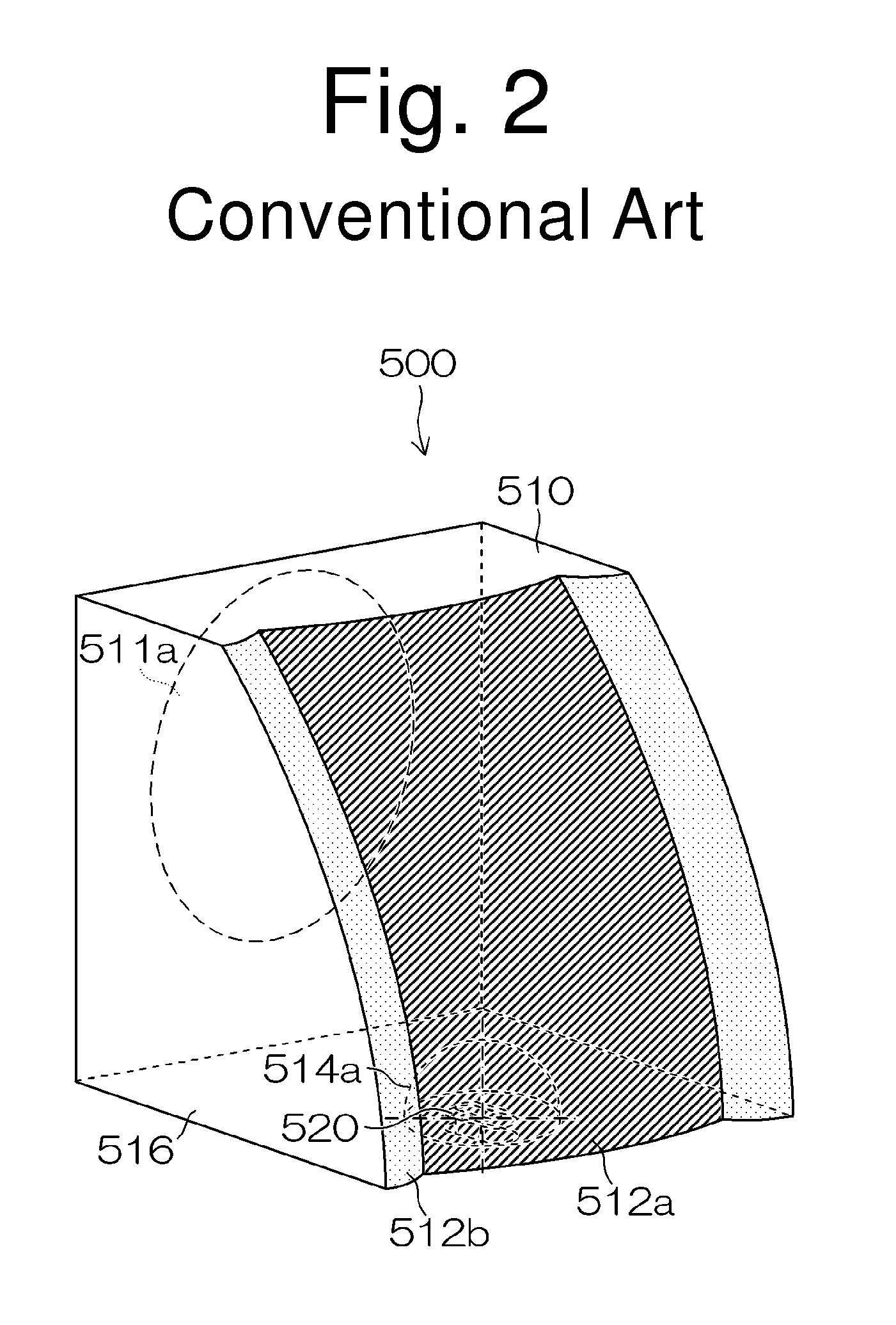
[0001]This application claims the priority benefit under 35 U.S.C. §119 of Japanese Patent Application No. 2009-146742 filed on Jun. 19, 2009, which is hereby incorporated in its entirety by reference.TECHNICAL FIELD[0002]The presently disclosed subject matter relates to a vehicle light, and in particular, to a vehicle light utilizing a lens body having optical surfaces, including an incident surface, a reflecting surface, and a projecting surface, configured to form a predetermined light distribution pattern, and connecting surfaces which shape and define the structure of the lens body by connecting the optical surfaces, but which do not engage in the formation of the light distribution pattern).BACKGROUND ART[0003]One conventional vehicle light 400 is illustrated as a conceptual diagram in FIG. 1. This type of vehicle light 400 can be configured to include a lens body 410 having a recess, and a light source (such as an LED light source) 420 disposed within the recess of the lens b...

Claims


Application Information

Patent Timeline
IPC IPC(8): B60Q1/04F21V5/00
CPCF21Y2115/10F21S41/148F21S41/28F21W2102/30F21W2102/00
Inventor OHNO, MASAFUMIOWADA, RYOTAROMYOJIN, NORIKATSU
Owner STANLEY ELECTRIC CO LTD
Learn More