
Combined helicopter landing pad and clamshell enclosure

a helicopter and enclosure technology, applied in the field of combined helicopter landing pads and clamshell enclosure inventions, can solve the problems of large aircraft areas exposed to the elements, tampering, wildlife,

Inactive Publication Date: 2010-12-23
HANAFIN BERNARD +1
View PDF19 Cites 13 Cited by
  • Summary
  • Abstract
  • Description
  • Claims
  • Application Information

AI Technical Summary

Benefits of technology

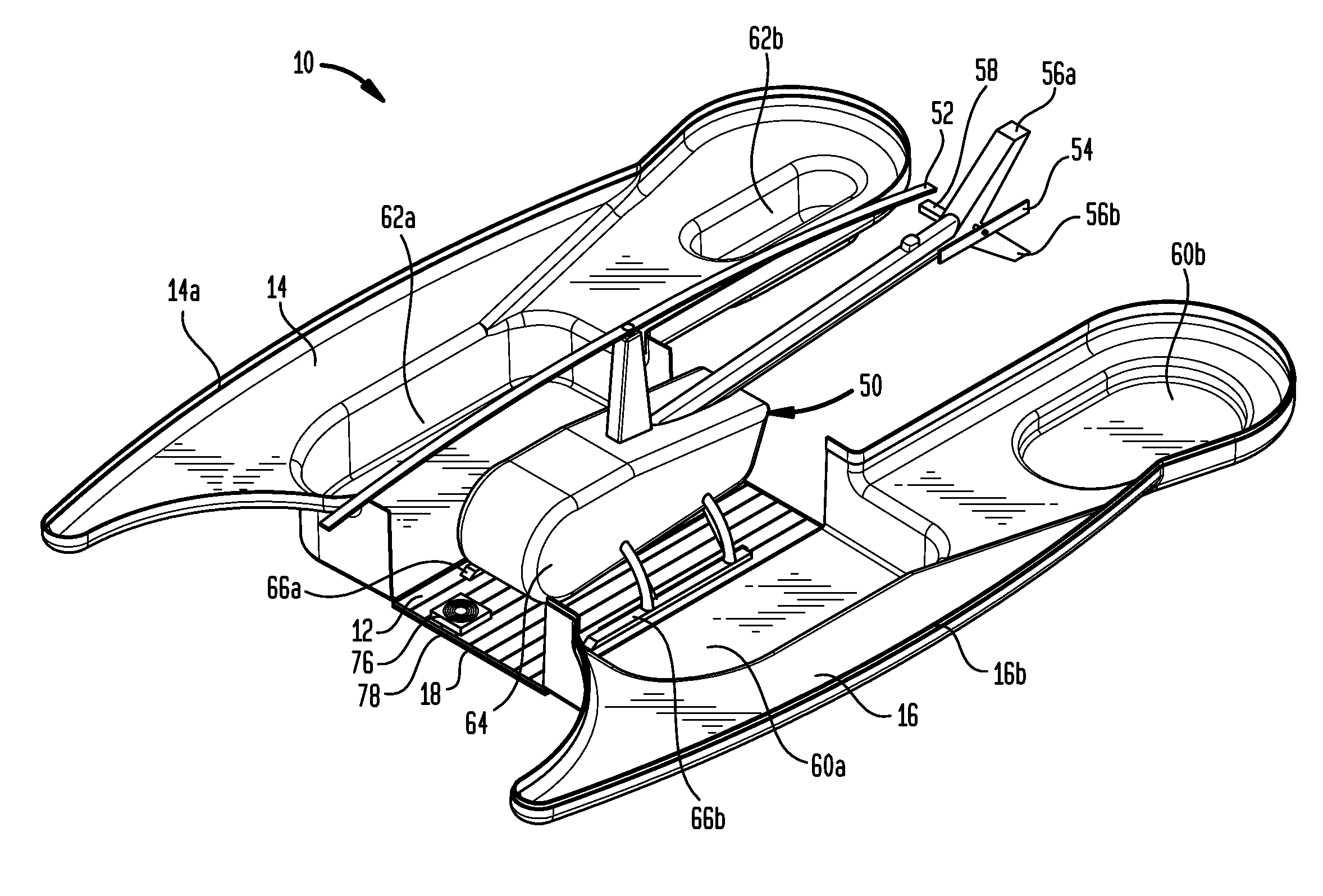
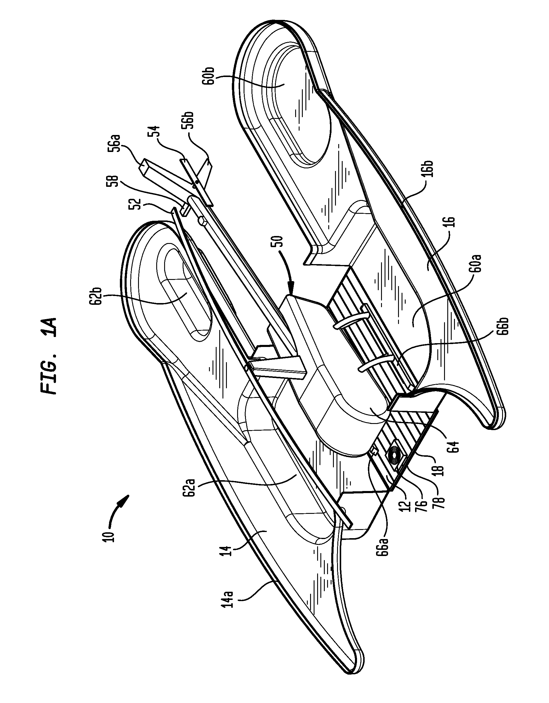
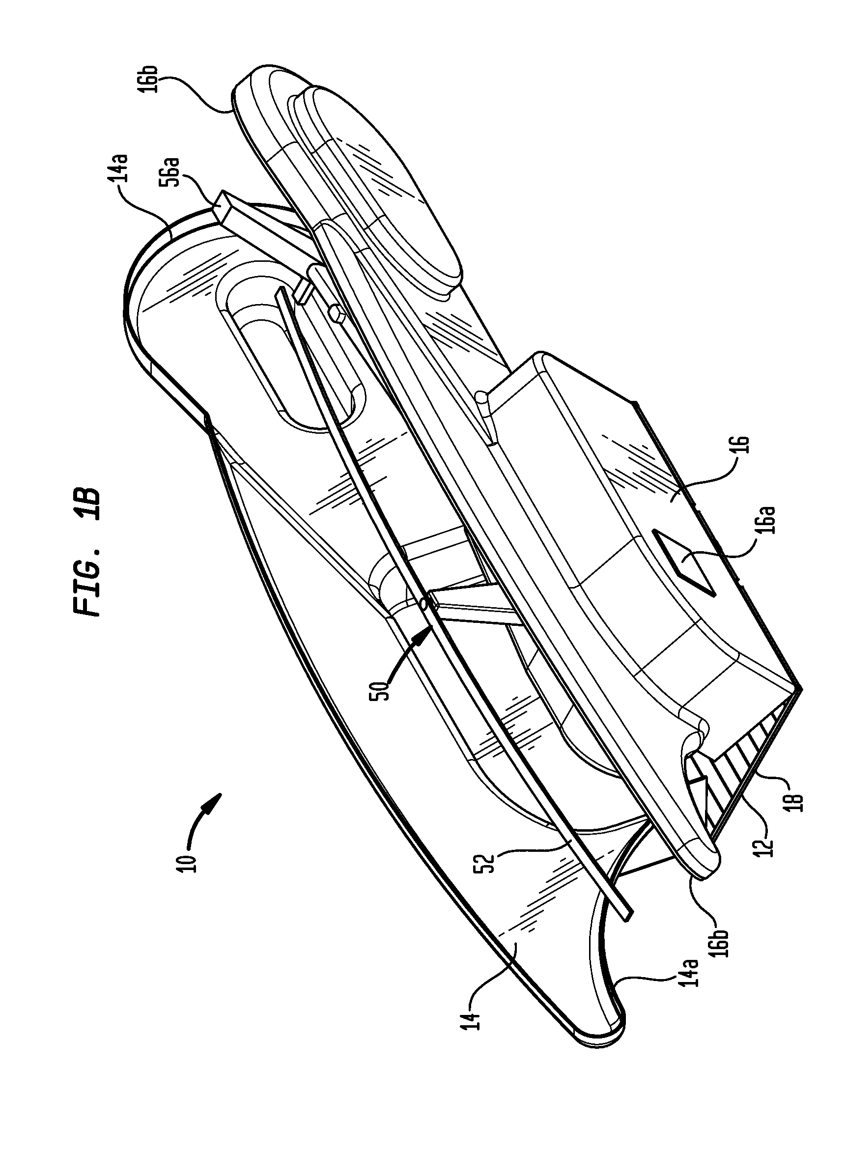
[0016]Once a pilot has landed and stopped rotor rotation on the deck, the pilot aligns the blades along the longitudinal axis of the helicopter (a standard practice) and secures same using the helicopter's rotor brake or other rotor strap. The pilot exits the helicopter and activates the mechanism to raise the two shells into a vertical position thus completely encapsulating the helicopter.
[0017]The pilot can now leave the area assured that the helicopter is secure from elements, potential tampering or wildlife infestation. As the pilot chooses, the entire closed assembly can be wheeled into a hangar, or a trailer, or left secured to the ground where the landing took place.

Problems solved by technology

Often, safe secure storage is desired but not available.
In many situations, the landing zone is too small to accommodate a shelter, or perhaps shelters are already occupied, or perhaps the landing zone is too remote to accommodate a permanent structure.
In such cases large areas of the aircraft are left exposed to the elements, tampering, or wildlife.
The aircraft cannot be flown into the hangar, nor is the propeller stored inside the structure, nor can the enclosed structure be moved without disassembling significant parts of the structure.
Both patents are limited to helicopters with more than two rotor blades and both limit the climatic conditions which are protected to direct sunlight.
While the invention described in that disclosure has some similarities to the current invention, in practice the device isn't practical.
In order to get any mechanical leverage the drive cylinders have to intrude substantially into the landing area thereby reducing the landing zone and presenting a landing hazard.
More importantly, the power required to open and close the housing sections is very significant and would put significant stresses on the structure rapidly leading to fatigue and structural failure.
None of the prior art permits the shipping of a helicopter in the same case as the aircraft can land onto.

Method used


Image

  • Combined helicopter landing pad and clamshell enclosure
  • Combined helicopter landing pad and clamshell enclosure
  • Combined helicopter landing pad and clamshell enclosure

Examples


embodiment 100

[0064]An alternative embodiment of the invention 100 having an electric drive system is shown in FIGS. 7A-7C. Embodiment 100 includes clamshell sections 14 and 16 and a base 102. Links 104a and 104b connect clamshell section 14 to front lead screw 106 and rear lead screw 128, respectively. Similarly, links 104c and 104d connect clamshell section 16 to front lead screw 106 and rear lead screw 128, respectively. As shown in FIG. 7C, front link 104a is attached by a pivotable member to clamshell section 14 at one end and to a pivotable member 124 attached to a traveling nut 122 at the other. The remaining links 104b, 104c and 104d are attached to the clamshell sections and traveling nuts in a similar manner. Nut 122 engages the threads 108 on the front lead screw 106. As shown in FIG. 7B, the front lead screw has threads 108 at one end and threads 110 at the other. The threads 108 and 110 are formed in the opposite sense or directions so that rotation of the lead screw 106 causes the t...

embodiment 200

[0067]Details of the expandable embodiment 200 are better understood by referring to FIG. 8B. A lead screw 208 is drivable by a wench type electric motor 210. Motor 210 includes a drive gear attached to a drive chain 212 which in turn drives a gear attached to lead screw 208. Another chain 214 which engages a gear on lead screw 208 drives the rear lead screw which operates in a similar manner. Drive motors 216 and 218 drive hollow drive rods or sleeves 220 and 222 respectively. Hollow drive sleeve 220 and 222 receive lead screw 208 so that as the landing pad 12 expands and contracts as the lead screw moves in and out of the hollow cavity in drive sleeves 220 and 222. Hollow sleeves 220 and 222 have threads on the exterior to receive traveling nuts similar to nut 122 shown in FIG. 7C. Also attached to sleeve 220 is a gear and drive chain 224 to provide power to the rear link 104b. Similarly, a chain 224 picks power off of sleeve 222 to drive rear link 104d.

[0068]In operation, if the...


PUM


Abstract

A clamshell case for enclosing a helicopter includes a base for supporting said helicopter, a first side section attached by a first hinge to one edge of the base, a second side section attached by a second hinge to the other edge of the base, and a drive system for rotating said side sections towards each other to substantially enclose said helicopter and substantially completely protect it from the weather and other damage.

Description

CROSS REFERENCE TO RELATED APPLICATIONS[0001]This application is a 371 National Phase of PCT Application No. PCT / US2009 / 030595 filed on Jan. 9, 2009 entitled “Combined Helicopter Landing Pad and Clamshell Enclosure,” and claims the priority of U.S. Provisional Patent application No. 61 / 019,892 filed on Jan. 9, 2008 by inventor Bernard Hanafin and entitled “Heli Hut Concept,” the entire contents and substance of which is incorporated herein by reference.FIELD OF INVENTION[0002]This invention relates to a combined helicopter landing pad and clamshell enclosure invention that permits a helicopter to make a safe landing directly into the landing pad and subsequently secures the helicopter from elements, potential tampering and wildlife infestation.DESCRIPTION OF RELATED ART[0003]Historically, helicopters are landed and, where safe secure storage is desired, the helicopter is somehow moved (or towed or pushed) into a suitable hangar. Often, safe secure storage is desired but not availabl...

Claims


Application Information

Patent Timeline
Patent Type & Authority Applications(United States)
IPC IPC(8): E04B1/344B64F3/00
CPCB64F1/005E01F3/00B64F1/125B64F1/007
Inventor HANAFIN, BERNARDVERMESI, GEORGE
Owner HANAFIN BERNARD
Learn More