
Bimetallic Diaphragm for Trapped Fluid Expansion

a technology of fluid expansion and bimetallic diaphragm, which is applied in the direction of sealing/packing, drilling pipes, and well accessories, etc., can solve the problems of liquid being trapped, leaking across the sealing of one or both wireline plugs, and liquid being trapped within the trapped fluid space, so as to reduce the volume of the cavity, prevent excessive pressure, and increase the volume of the trapped fluid space

Inactive Publication Date: 2010-12-09
VETCO GRAY
View PDF9 Cites 5 Cited by
  • Summary
  • Abstract
  • Description
  • Claims
  • Application Information

AI Technical Summary

Benefits of technology

[0006]A subsea wellhead assembly has a tubular member with a passage containing first and second plugs. The plugs define a sealed trapped fluid space between them that is filled with a liquid. A cavity is formed in the first plug. A barrier is mounted to the first plug sealingly over the cavity and in fluid communication with the liquid in the trapped fluid space. The barrier is movable repeatedly between inner and outer positions in response to temperature changes. The inner position reduces a volume of the cavity and increases a volume of the trapped fluid space to prevent excessive pressure occurring due to a temperature increase. The outer position increases the volume of the cavity and decreases the volume of the trapped liquid space to avoid a vacuum occurring.

Problems solved by technology

Normally, there is no outlet leading to the space in the passage between the plugs, thus the liquid will be trapped.
The expansion would cause the pressure within the trapped fluid space to rise and could result in leakage across the seals of one or both of the wireline plugs.
This reduction in pressure could cause sea water to be drawn across the seals of the upper plug.
The cycling of temperature can damage the seals, reducing the effectiveness of the plugs as being pressure barriers.

Method used


Image

  • Bimetallic Diaphragm for Trapped Fluid Expansion
  • Bimetallic Diaphragm for Trapped Fluid Expansion
  • Bimetallic Diaphragm for Trapped Fluid Expansion

Examples


Embodiment Construction

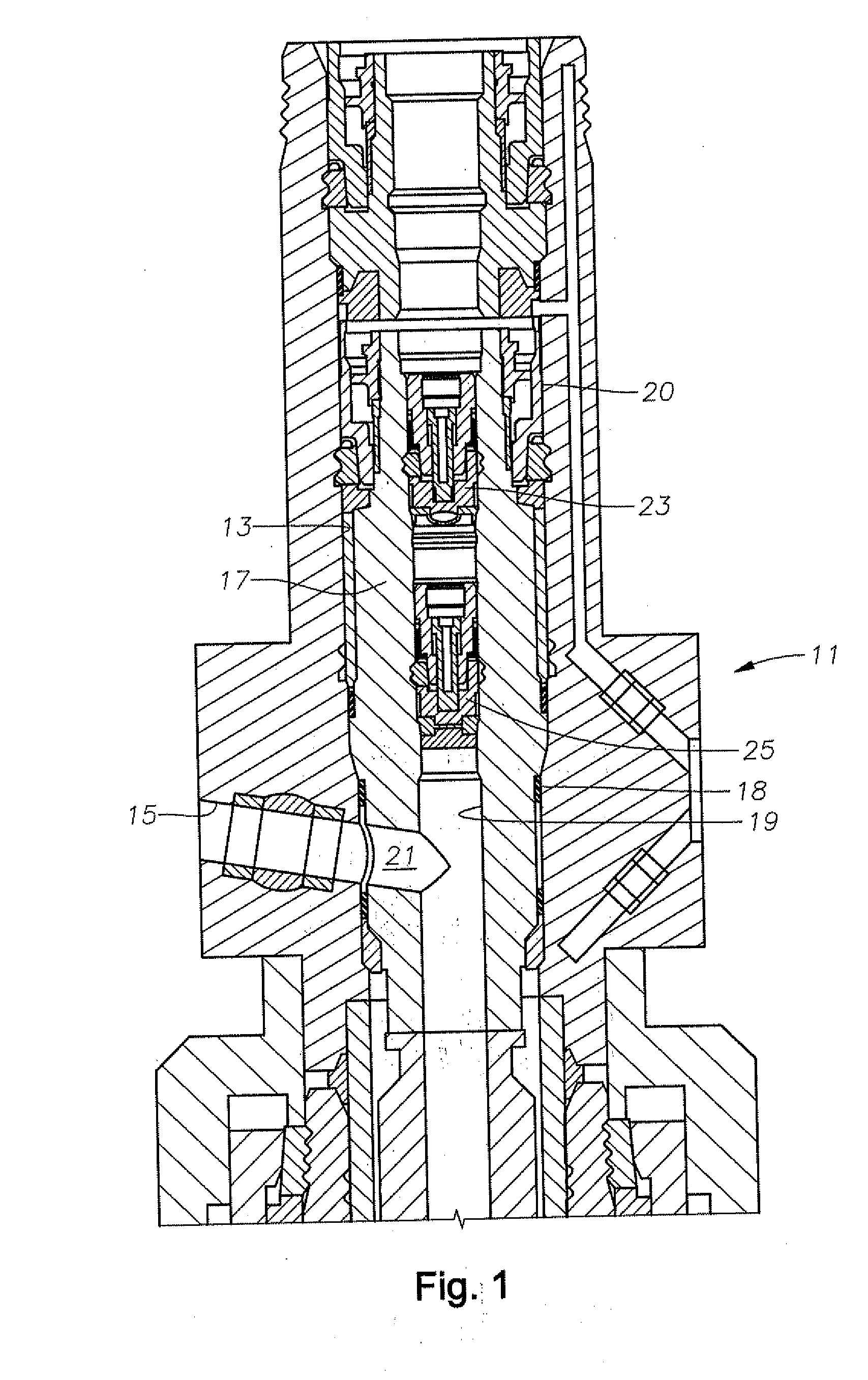
[0011]Referring to FIG. 1, a production tree 11 is installed at the seafloor at the upper end of a well. Production tree 11 has a bore 13 that extends through it along the longitudinal axis of tree 11. A production outlet 15 extends from tree bore 13 laterally outward. A tubing hanger 17 lands in tree bore 13 and is secured to a string of production tubing (not shown) for the flow of well fluid from the well. Tubing hanger 17 has an axial passage 19, and a lateral passage 21 extends laterally outward from axial passage 19. Lateral passage 21 registers with production outlet 15. Seals 18 above and below lateral passage 21 seal the junction of tubing hanger lateral passage 21 with production outlet 15. A lockdown mechanism 20 locks tubing hanger 17 in tree bore 13. Tree 11 has various valves and other equipment for controlling production of the well.

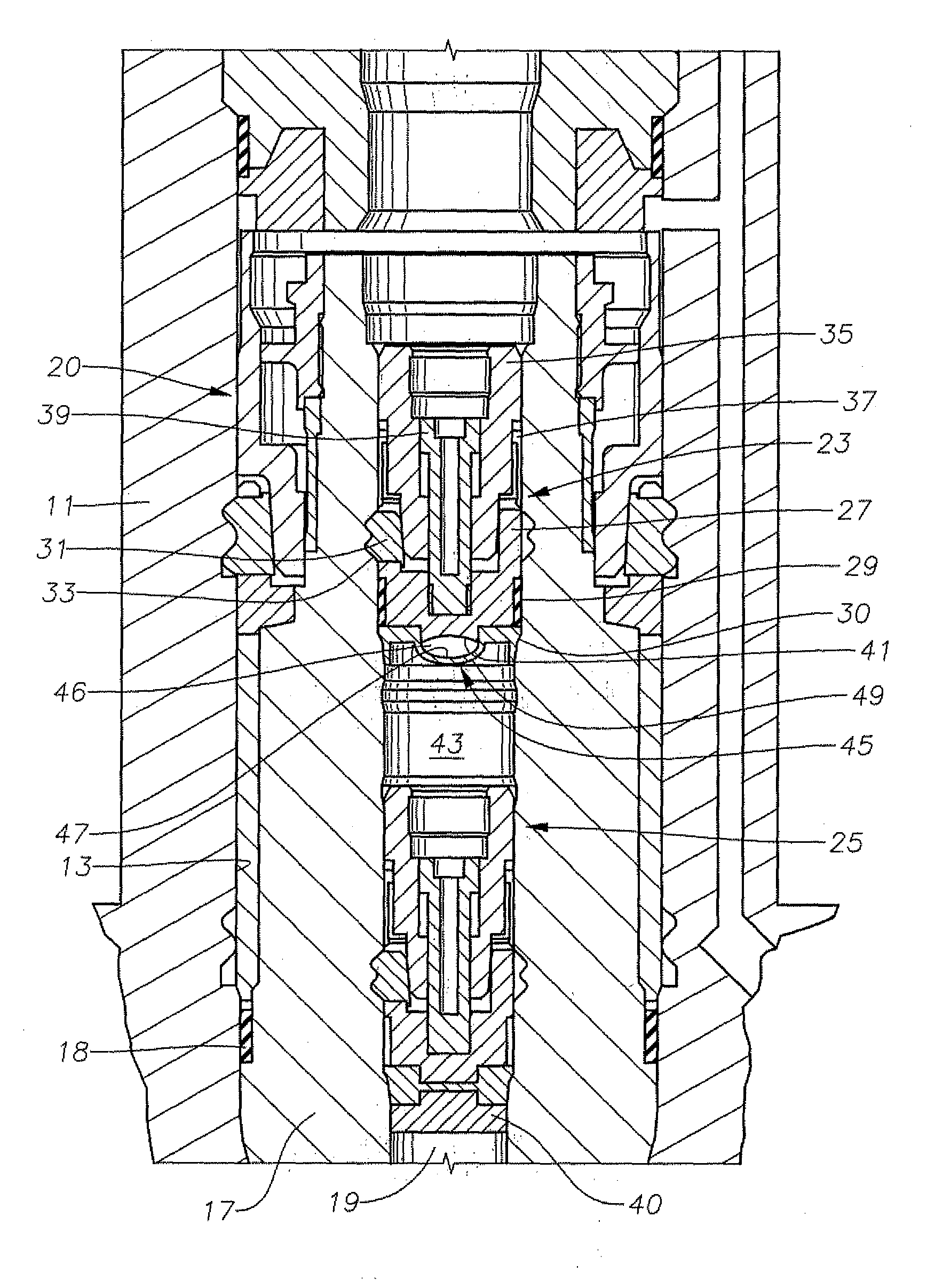
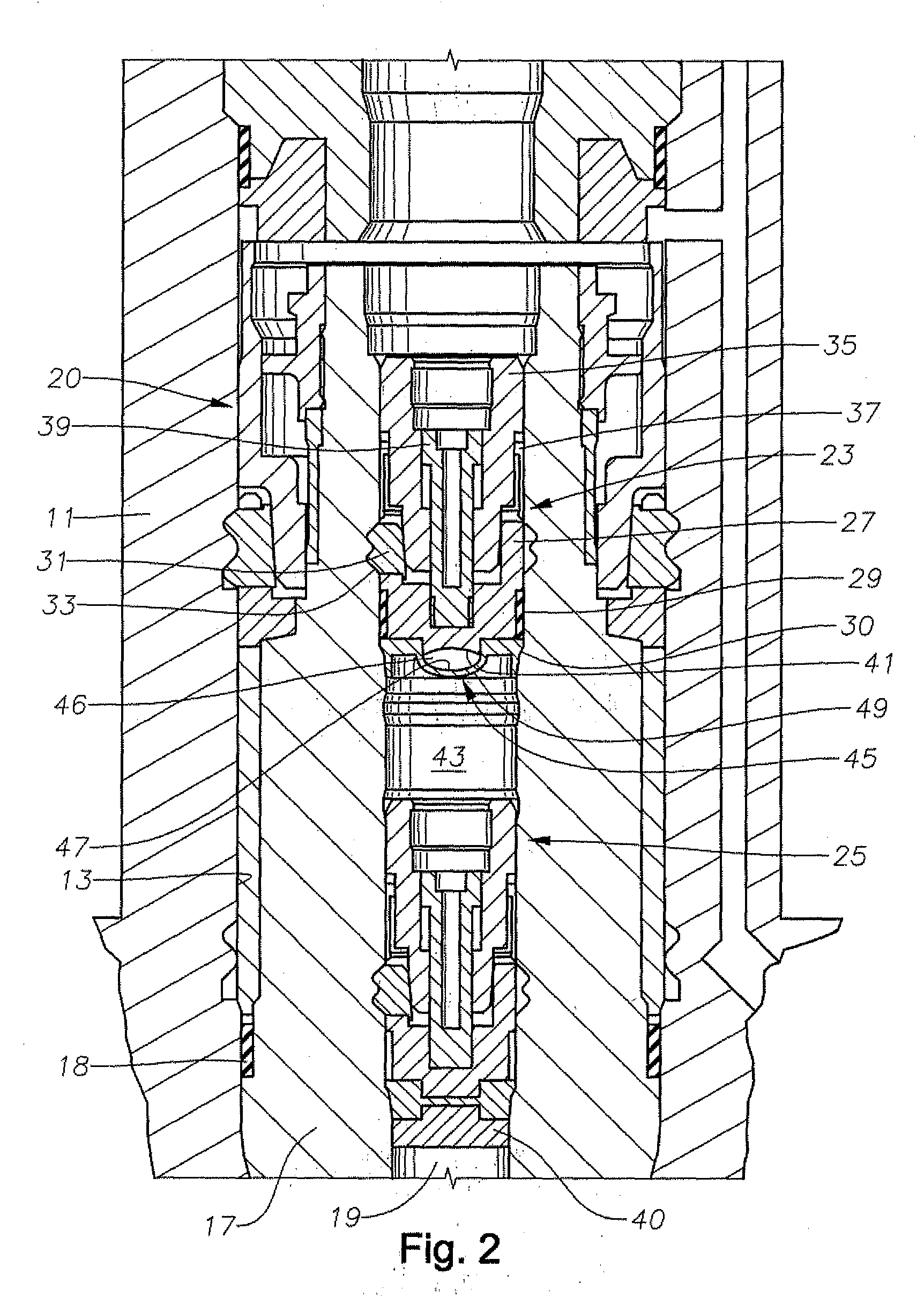
[0012]Referring to FIG. 2, in this embodiment, an upper crown plug 23 and a lower crown plug 25 are installed in tubing hanger axial pass...


PUM


Abstract

A subsea well tubular member has an axial passage with upper and lower retrievable plugs releasably mounted in the passage, the plugs having ends facing each other. A cavity is formed on one of the ends of one of the plugs. A movable barrier is mounted sealingly over the cavity, the barrier being movable repeatedly between inner and outer positions in response to temperature changes. The inner position reduces a volume of the cavity and increases a volume of a trapped fluid space between the ends of the plugs. The outer position increases the volume of the cavity and decreases the volume of the trapped fluid space. The barrier has two metallic layers with different coefficients of expansion.

Description

CROSS-REFERENCE TO RELATED APPLICATION[0001]This application claims priority to provisional application 61 / 183,699, filed Jun. 3, 2009.FIELD OF THE INVENTION[0002]This invention relates in general to subsea well production trees, and in particular to a bimetallic diaphragm located in an area containing a trapped volume of fluid subject to expansion and contraction due to temperature changes.BACKGROUND OF THE INVENTION[0003]One type of subsea wellhead assembly has a production tree mounted to a wellhead housing at the upper end of the well. In one type of production tree, referred to as a horizontal tree, a tubing hanger lands in the production tree. The tubing hanger supports a string of tubing and has an axial passage that receives the flow of well fluid. The axial passage has a lateral outlet between upper and lower ends of the axial passage. The lateral outlet registers with a lateral outlet in the production tree. At least one plug is secured in the axial passage above the later...

Claims


Application Information

Patent Timeline
Patent Type & Authority Applications(United States)
IPC IPC(8): E21B43/00E21B33/04
CPCE21B33/035E21B33/04
Inventor BUCKLE, KEVIN G.
Owner VETCO GRAY
Learn More