
Method and apparatus for providing user interface based on contact position and intensity of contact force on touch screen

a touch screen and user interface technology, applied in the direction of instruments, computing, electric digital data processing, etc., can solve the problems of limited functions of the user interface in the touch input device, and the inability to implement a wide range of functions through the user interface using a conventional touch input device,

Inactive Publication Date: 2010-12-02
KOREA RES INST OF STANDARDS & SCI
View PDF4 Cites 151 Cited by
  • Summary
  • Abstract
  • Description
  • Claims
  • Application Information

AI Technical Summary

Benefits of technology

[0019]According to another aspect of the present invention, there is provided an apparatus for providing a user interface based on a contact position and an intensity of contact force on a touch screen, comprising: a touch input unit 100 comprising tactile sensors 140 each configured to receive a touch input signal generated by a touch of a user's pointing object 1; a position processing unit 200 configured to identify a contact position corresponding to the received touch input signal; an intensity processing unit 300 configured to analy...

Problems solved by technology

In other words, since the touch screen is configured to detect only a contact position by determining only whether the pointing object has touched the touch screen, a user interface in a touch input device provides only limited functions.
Accordingly, a variety of functions cannot be implemented through a user interface using a conventional touch input device.

Method used


Image

  • Method and apparatus for providing user interface based on contact position and intensity of contact force on touch screen
  • Method and apparatus for providing user interface based on contact position and intensity of contact force on touch screen
  • Method and apparatus for providing user interface based on contact position and intensity of contact force on touch screen

Examples


Embodiment Construction

[0035]Some embodiments of the present invention will now be described in detail with reference to the accompanying drawings.

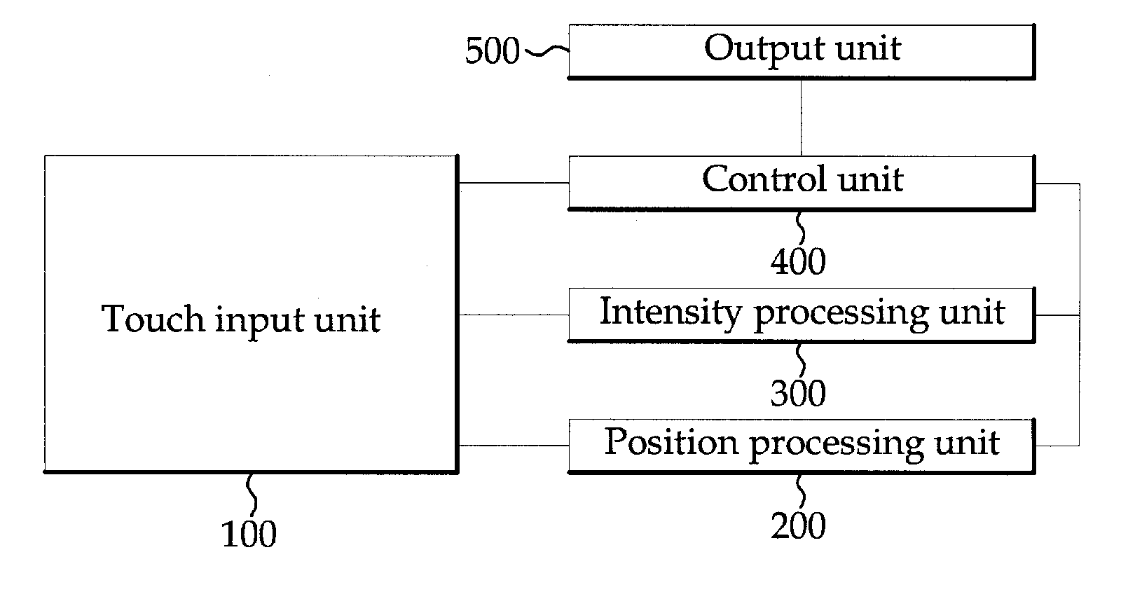
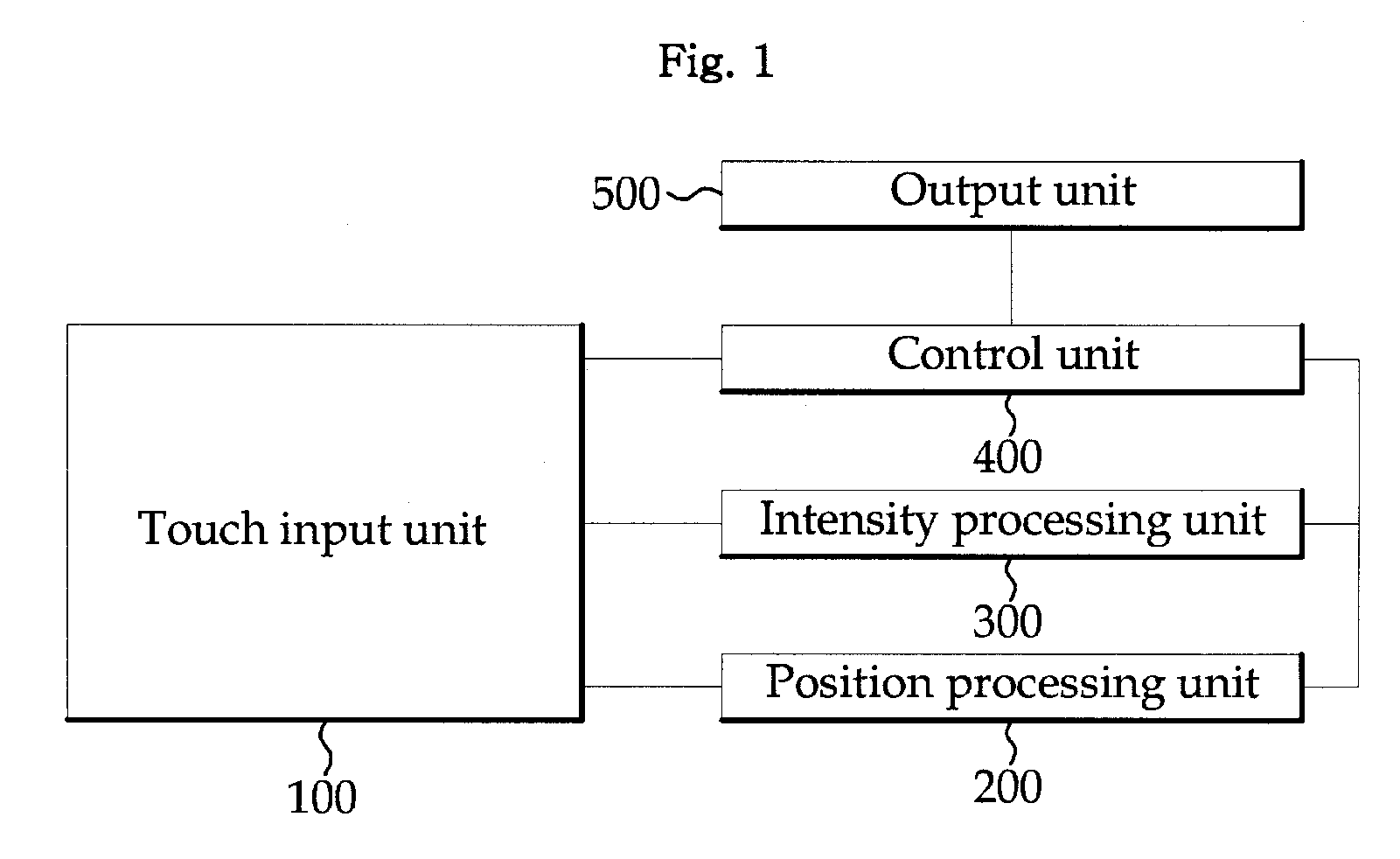
[0036]FIG. 1 is a block diagram showing the construction of a user interface apparatus according to an exemplary embodiment of the present invention. Referring to FIG. 1, the user interface apparatus according to the exemplary embodiment of the present invention includes a touch input unit 100, a position processing unit 200, an intensity processing unit 300, a control unit 400, and an output unit 500.

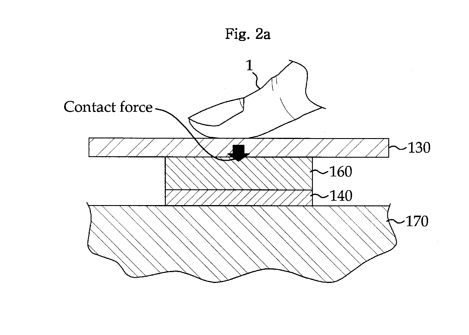
[0037]The touch input unit 100 is configured to receive a touch input signal detected by a touch screen 130 configured to detect a position and force at the same time when a user's pointing object 1 (e.g., a stylus pen or a finger) touches the touch screen 130. Although the present embodiment illustrates the touch screen for detecting a position and force using tactile sensors 140 based on a contact resistance method, the touch input unit 100 may have a constructi...


PUM


Abstract

A method and apparatus are disclosed providing a user interface using a touch input unit comprising a touch screen configured to detect a contact position and a contact force. The method comprises a step of the touch input unit receiving a touch input signal generated by a touch of a user's pointing object, a step of executing a step of a position processing unit identifying a contact position, corresponding to the received touch input signal, and a step of an intensity processing unit analyzing an intensity pattern of contact force, corresponding to the received touch input signal, simultaneously or sequentially, a step of a control unit determining an event corresponding to the touch input signal based on the identified contact position and the analyzed intensity pattern of contact force, and a step of an output unit outputting the determined event to a display screen.

Description

FIELD OF THE INVENTION[0001]The present invention relates to a method and apparatus for providing a user interface through a touch screen and, more particularly, to a method and apparatus for providing a user interface based on a contact position and the intensity of contact force of a pointing object touching a touch screen.BACKGROUND OF THE INVENTION[0002]In general, a touch screen is an input device that replaces the keyboard and the mouse and is configured to have a touch panel capable of detecting a user's touch attached on a monitor (e.g., a Liquid Crystal Display (LCD)), thereby enabling a user to perform a desired task. The touch screen is being used in, particularly, small-sized terminals having a limited size, such as portable phones, PMP, or MP3 players.[0003]This touch screen is being used in the state of ON / OFF because consecutive data cannot be obtained in proportion to force by the contact of a pointing object (e.g., a stylus pen and a finger). In other words, since t...

Claims


Application Information

Patent Timeline
IPC IPC(8): G06F3/041
CPCG06F3/04883G06F2203/04806G06F3/0414G06F3/0416G06F3/0488G06F3/14G06F3/0412
Inventor KIM, JONG HOKIM, MIN SEOKPARK, YON-KYUKANG, DAE IM
Owner KOREA RES INST OF STANDARDS & SCI
Learn More