
Butterfly valve plate sealing assembly

a technology of sealing assembly and valve plate, which is applied in the direction of engine seals, valve arrangements, plug valves, etc., can solve the problems of increased closing force, misalignment and expansion of the downstream portion of the sealing ring

Active Publication Date: 2010-12-02
HONEYWELL INT INC
View PDF9 Cites 3 Cited by
  • Summary
  • Abstract
  • Description
  • Claims
  • Application Information

AI Technical Summary

Benefits of technology

The patent describes a butterfly valve sealing assembly that includes a sealing ring and a retention spacer to prevent the sealing ring from expanding when exposed to pressurized fluid. This assembly helps to improve the sealing performance of the butterfly valve and ensure its durability over a long period of use.

Problems solved by technology

In particular, the flow of fluid through the channel may cause a downstream portion of the sealing ring to expand and become misaligned relative to the sealing ring groove.
When the butterfly valve plate is then closed, increased closing forces may exist as a result of the misaligned sealing ring.

Method used


Image

  • Butterfly valve plate sealing assembly
  • Butterfly valve plate sealing assembly
  • Butterfly valve plate sealing assembly

Examples


Embodiment Construction

[0018]The following detailed description of the inventive subject matter is merely exemplary in nature and is not intended to limit the inventive subject matter or the application and uses of the inventive subject matter. Furthermore, there is no intention to be bound by any theory presented in the preceding background of the inventive subject matter or the following detailed description of the inventive subject matter.

[0019]It is contemplated that the present invention is particularly well suited for use with butterfly type valves, more particularly with butterfly type valves that are used in cabin environmental control systems. However, the present invention may also be applicable in other types of valves where a part or assembly rotates about a shaft, the sealing assembly includes dual components for sealing about a periphery of the rotating assembly and it is desirable to prevent unwanted movement of the sealing component from about the periphery of the rotating assembly when un...


PUM


Abstract

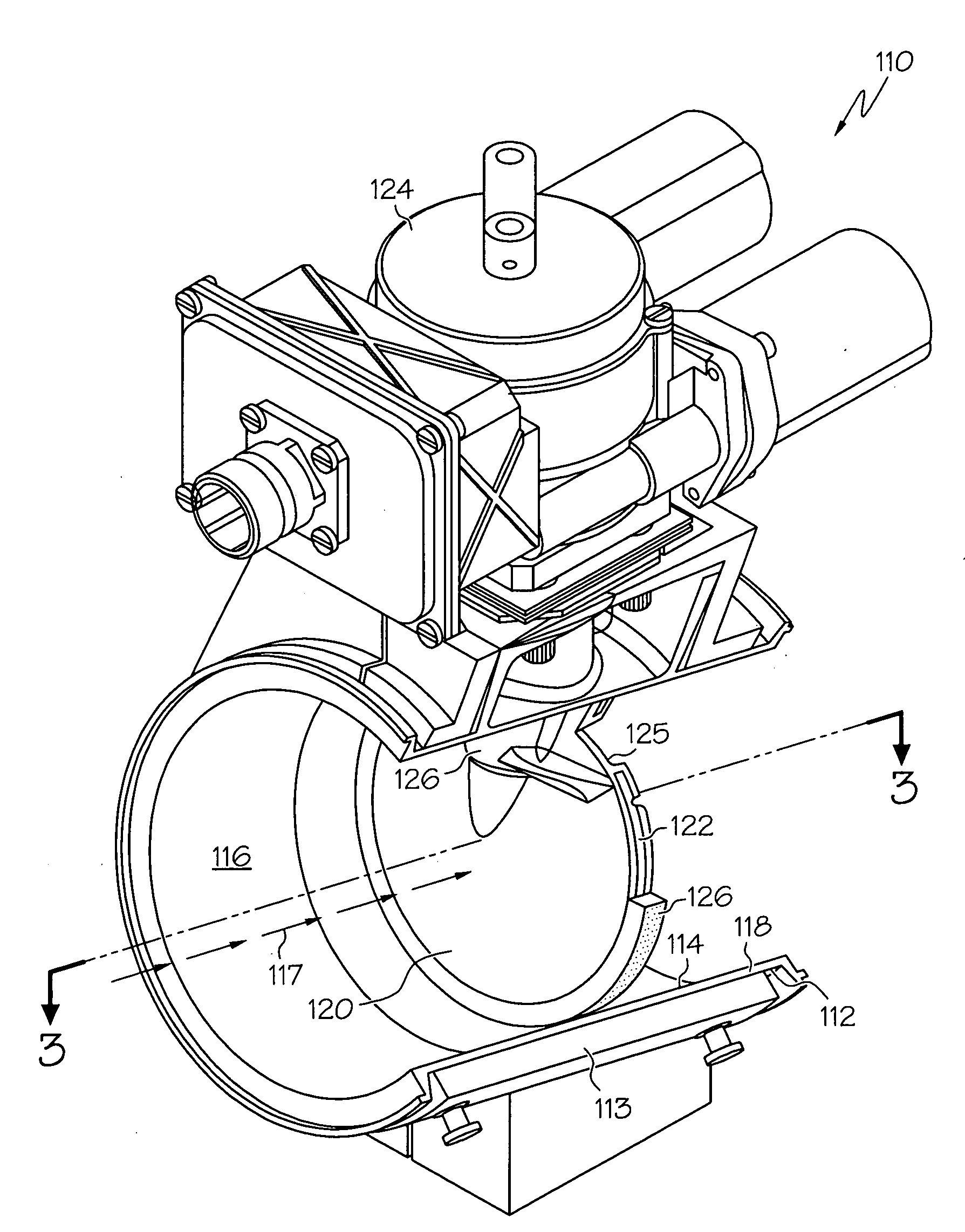
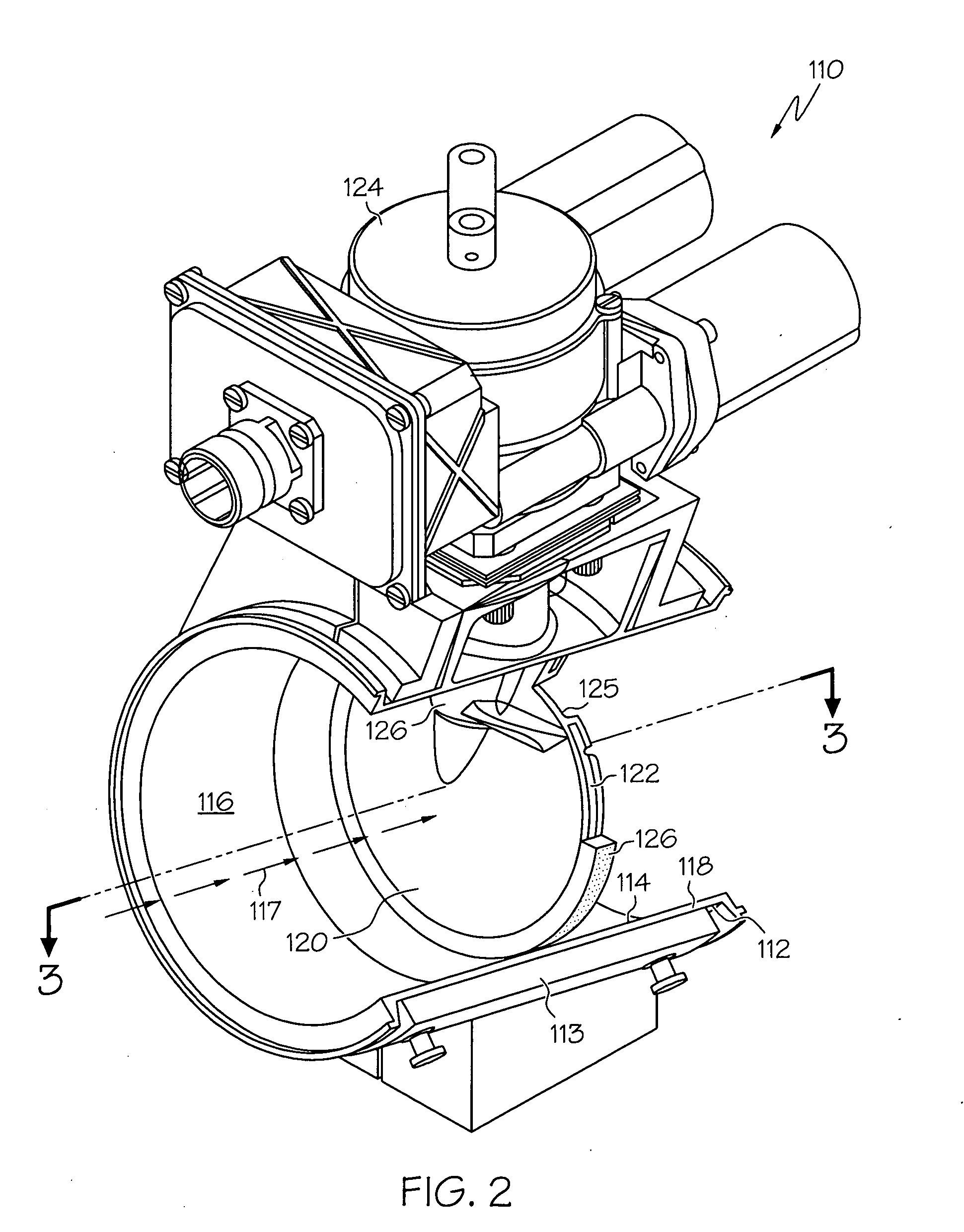
Butterfly valve plate sealing assemblies are provided that include a sealing ring and a retention spacer disposed at least partially within a sealing ring groove formed about a periphery of a butterfly valve plate. The sealing ring includes a first portion, a second portion configured substantially perpendicular to the first portion, and a substantially L-shaped cross-section. The sealing ring is positioned at least partially within a groove opening and a groove body defining the sealing ring groove. The retention spacer is positioned at least partially within the groove opening and adjacent the first portion of the sealing ring. The retention spacer is configured to limit expansion of the sealing ring when under the influence of a pressurized fluid flow. The second portion of the sealing ring may be configured to optimize stiffness for a desired sealing ring tension.

Description

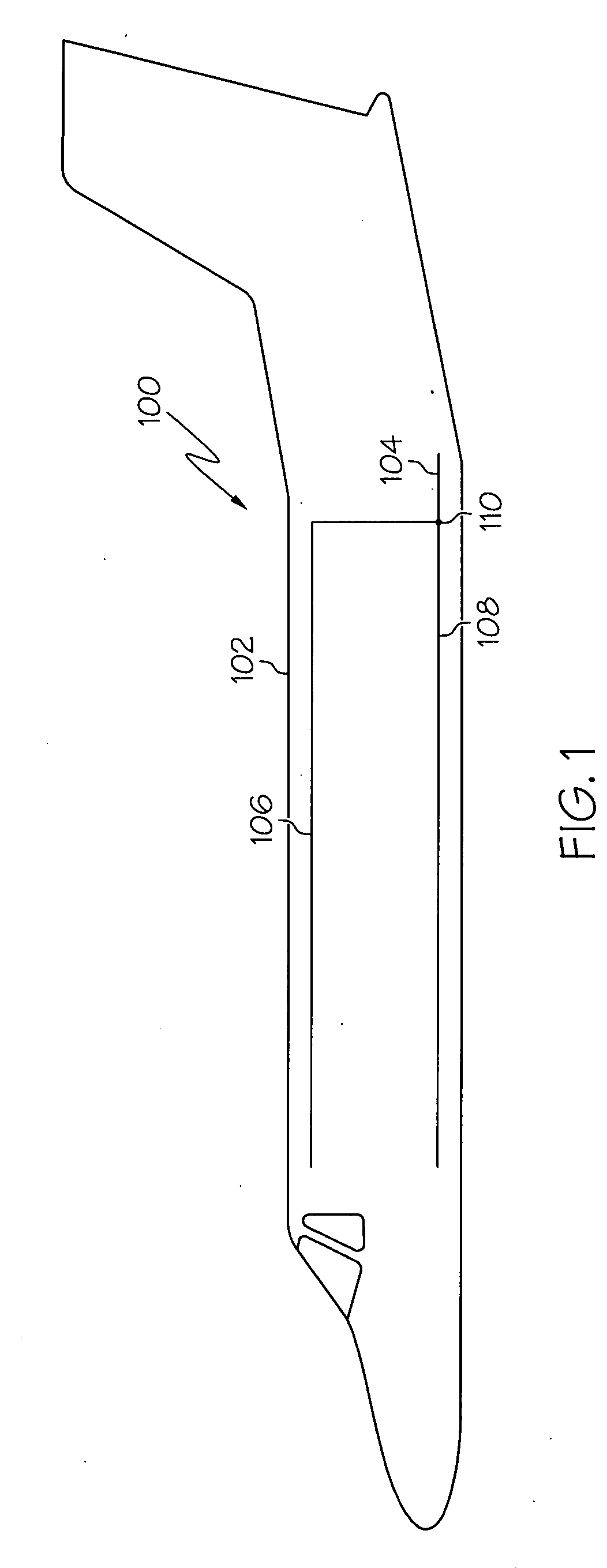
TECHNICAL FIELD[0001]The inventive subject matter relates to butterfly valve assemblies and, more particularly, to a butterfly valve sealing ring assembly for use with a single piece butterfly plate.BACKGROUND[0002]Valves may be employed in any one of numerous situations. For example, valves may be used in an air distribution system to allow, control, or shut off airflow from one portion of an aircraft's ducting to another. In this regard, pneumatic valves may be disposed in a duct between an air source and one or more outlets to control the flow of the received air that is distributed to other components or areas in the aircraft, such as, for example, the environmental control system or an aircraft cabin.[0003]One exemplary type of pneumatic valve that has been employed in aircraft is a butterfly valve. A butterfly valve is typically made up of a valve flowbody and a butterfly plate. The valve flowbody may be made of a rigid material, such as metal, and includes a channel or bore t...

Claims


Application Information

Patent Timeline
Patent Type & Authority Applications(United States)
IPC IPC(8): F16K1/22
CPCF16K1/2261
Inventor KOLB, CRAIGPANTIER, DAVIDLABENZ, JOELMARTIN, SCOTT
Owner HONEYWELL INT INC
Learn More