
Walking assistance device

a technology of assistance device and latch mechanism, which is applied in the field of walking assistance device, can solve the problems of user experience some difficulty in attaching the drive unit to the pelvis, difficulty in wearing the pelvis frame, and relative heavy drive unit, and achieve the effect of preventing the inadvertent release of the latch mechanism, facilitating the actuation of the latch member, and enhancing the external appearance of the devi

Inactive Publication Date: 2010-11-25
HONDA MOTOR CO LTD
View PDF6 Cites 49 Cited by
  • Summary
  • Abstract
  • Description
  • Claims
  • Application Information

AI Technical Summary

Benefits of technology

[0008]In view of such problems of the prior art, a primary object of the present invention is to provide a walking assistance device that can be worn and removed with ease.
[0009]A second object of the present invention is to provide a walking assistance device that can be worn and removed without requiring a help from another person.
[0010]A third object of the present invention is to provide a walking assistance device that can transmit the power generated by a rotary power generator to a power transmitting arm connected to an output end of the rotary power generator.

Problems solved by technology

However, according such a convention arrangement, the user is required to handle the relatively heavy drive unit when attaching and detaching the drive unit to and from the pelvic frame.
Therefore, the user experiences some difficult in attaching the drive unit to the pelvic frame, after wearing the pelvic frame, by himself or herself, and often requires a help of a caretaker when attaching the drive unit to the pelvic frame.
The user may also be able to attach the drive unit to the pelvic frame before wearing the pelvic frame, but may experience some difficulty in wearing the pelvic frame which is burdened by the weight of the drive unit.

Method used


Image

  • Walking assistance device
  • Walking assistance device
  • Walking assistance device

Examples


Embodiment Construction

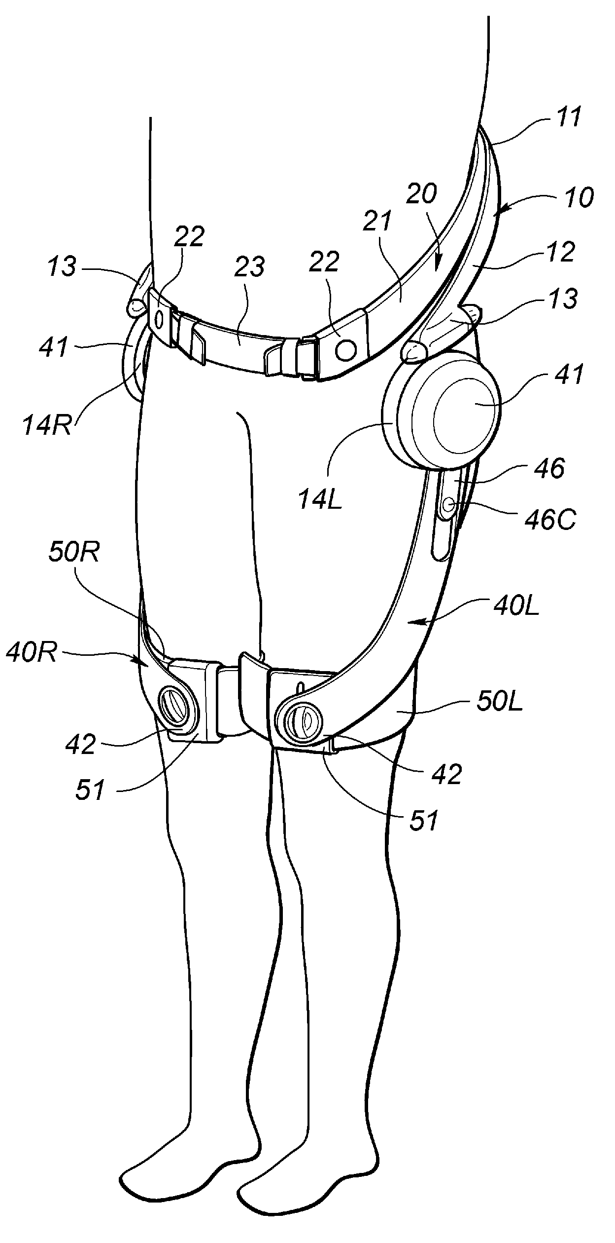
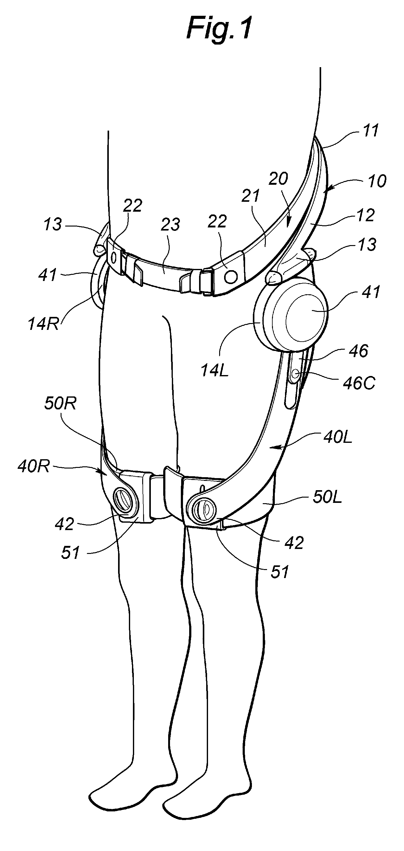
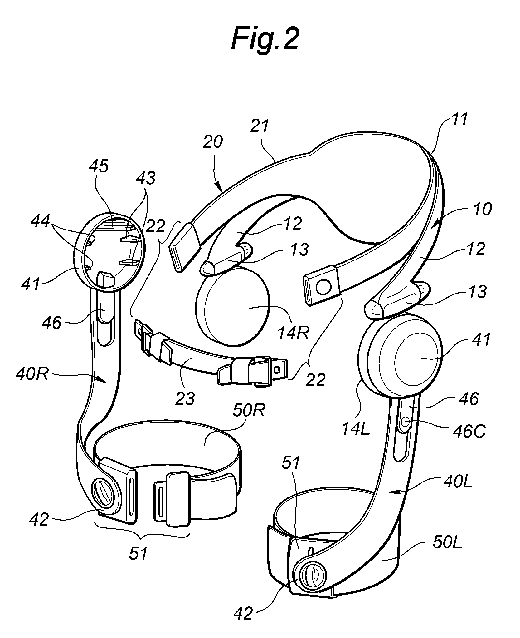
[0028]A walking assistance device embodying the present invention is described in the following with reference to FIGS. 1 to 8. The illustrated walking assistance device comprises a pelvic frame 10 that can be detachably attached to a pelvic part of a user by using a belly belt 20. The pelvic frame 10 essentially consists of a relatively stiff member made of molded plastic material such as carbon reinforced plastic material, and includes a middle part 11 located centrally on a lower back portion of the user and a pair of side extensions 12 extending from the middle part 11 along either side of the pelvis of the user so as to define a shape of letter-C as seen in plan view.

[0029]The belly belt 20 is made of flexible material having a relatively high tensile strength such as woven fabric, synthetic leather, natural leather and plastic, and includes a pair of belt main sections 21 connected to the middle part 11 of the pelvic frame 10 and extending along the back and both sides of the ...


PUM


Abstract

A walking assistance device comprises a pelvic frame (10) extending from a lower back to each lateral side of a user, and a belly belt (20) for securing the pelvic frame in position. A power generator (30) is attached to each lateral side of the pelvic frame. A power transmitting arm (40) can be attached to an output member (33) of the power generator simply by hooking an upper part of a base end (41) of the power transmitting arm onto an upper groove (38) of the output member, and pushing a latch member or a slider (46) provided in a lower part of the base end onto a lower groove (39) of the output member. Therefore, the user wearing the pelvic frame (10) can easily attach the power transmitting arm (40) to the output end of the power generator (30) by using a single hand with ease and without requiring a help from a caretaker.

Description

[0001]TECHNICAL FIELD[0002]The present invention relates to a walking assistance device, and in particular to a walking assistance device incorporated with a power actuator or a rotary power generator to provide a walking assistance force to a lower limb of a user.BACKGROUND OF THE INVENTION[0003]There have been proposes various forms of walking assistance devices that assist movement of a lower limb of a person who has become unable to walk by himself or herself owing to a diminished muscle power that is typically caused by an injury, disease or aging. Such a device may be used not only for aiding the effort required for the user to walk but also for aiding the rehabilitation of the user who is in the process of regaining the capability to walk.[0004]Such a device typically comprises a C-shaped pelvic frame extending from a lower back of the user to either side of the pelvis, a pair of power actuators attached to corresponding side parts of the pelvic frame and a pair of power tran...

Claims


Application Information

Patent Timeline
IPC IPC(8): A61H1/00
CPCA61H3/008A61H2201/165B25J9/0006A61H1/0244A61H2201/1676A61H2201/1215A61H2201/163A61H2201/1642A61H3/00
Inventor SHIMIZU, HIDEONODA, TATSUYAKOYAMA, TAIJI
Owner HONDA MOTOR CO LTD
Learn More