
Recording apparatus

a recording apparatus and a technology for recording, applied in the direction of electrographic process, instruments, transportation and packaging, etc., can solve the problems of large loss of time, difficult to independently change the driving speed of the roller, and difficult to control the roller independently of the other roller, etc., to achieve the effect of reducing tim

Active Publication Date: 2010-11-25
SEIKO EPSON CORP
View PDF8 Cites 25 Cited by
  • Summary
  • Abstract
  • Description
  • Claims
  • Application Information

AI Technical Summary

Benefits of technology

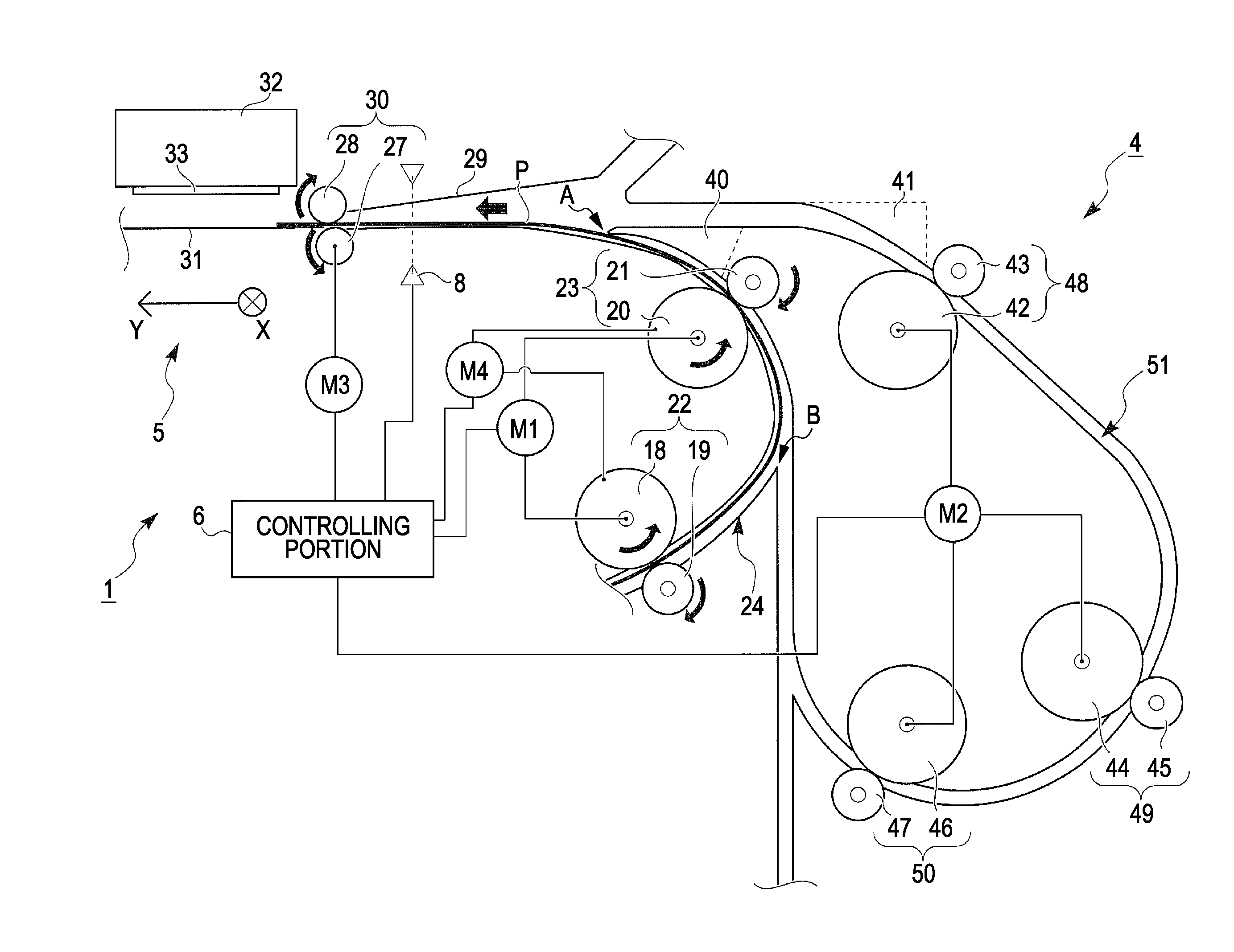
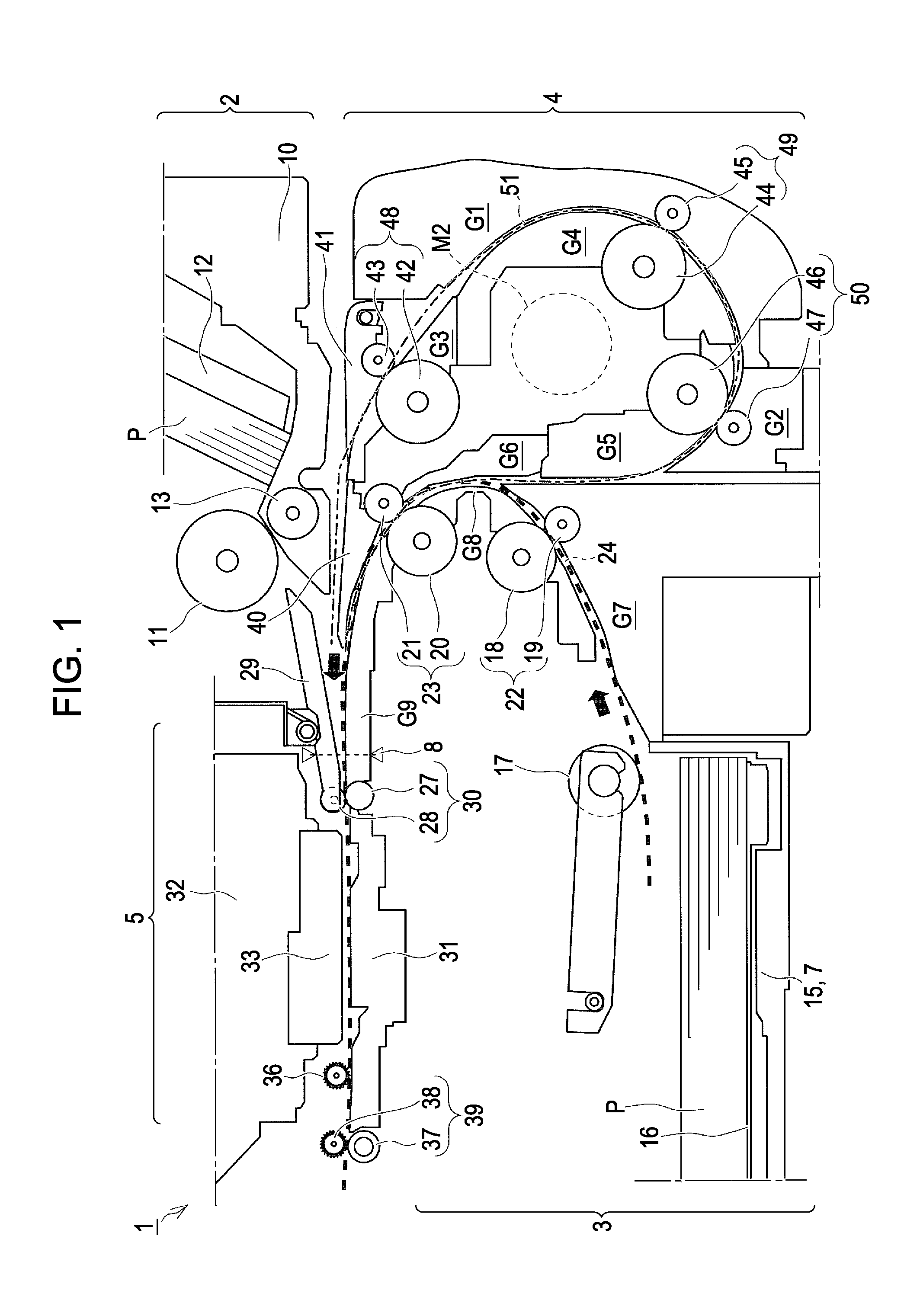
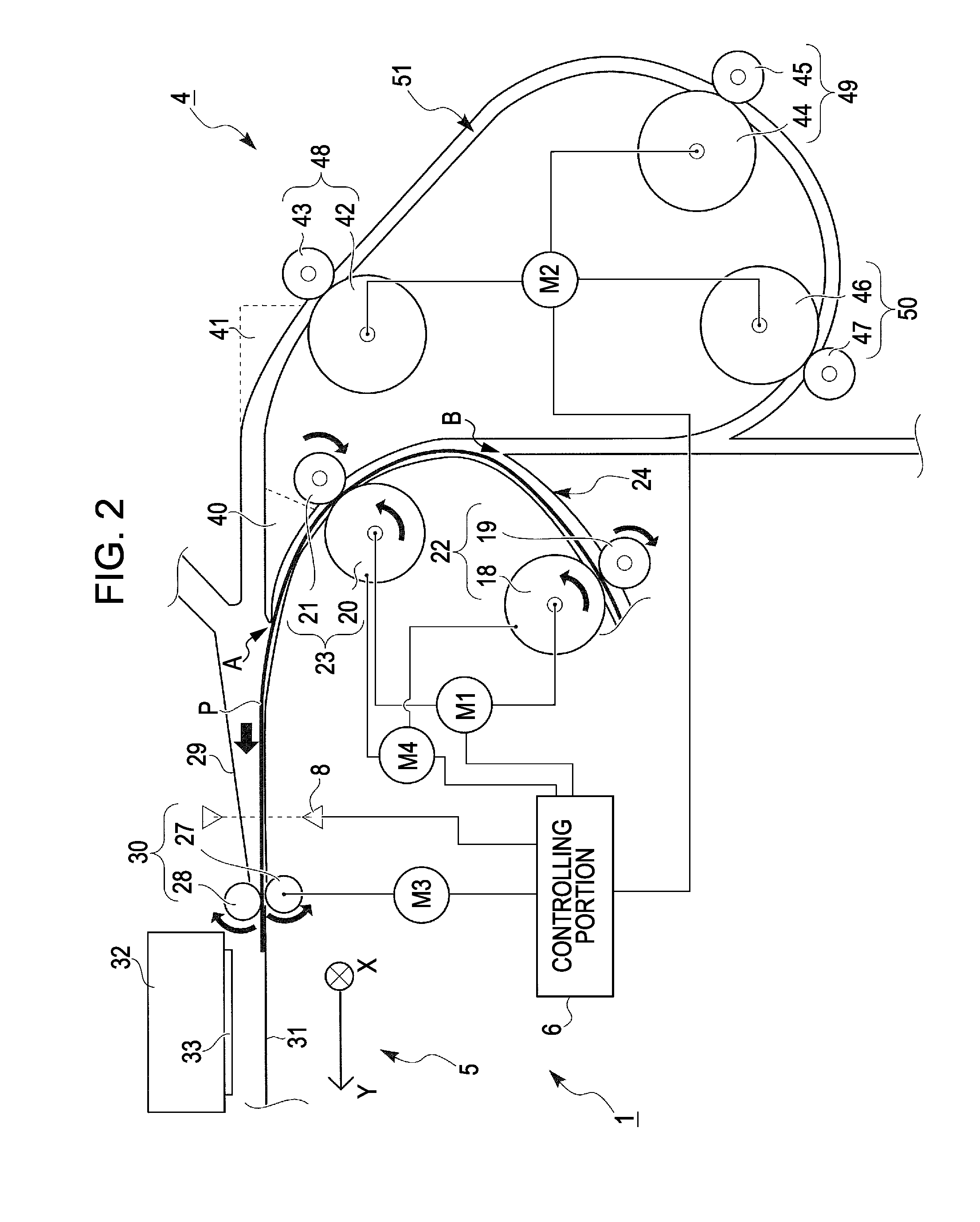
[0010]An advantage of some aspects of the invention is to provide a recording apparatus that considers the loss of time from completion of the recording on the one surface of a medium to the start of the recording on the other surface of the recording apparatus for executing double-sided printing.
[0014]In addition, the driving speed of the first motor is set to be a high speed so that it is changed from the transport speed V1 to the transport speed V2. Thus, the structure of the embodiment can obtain the above-described working effects with low costs as compared to a structure in which the second transport path is branched into a plurality of paths, the lengths of the paths are different from each other, and the medium to be recorded is distributed to the branched path according to the length of the medium to be recorded. That is to say, it is possible to reduce a loss of time and improve the throughput.
[0017]On the other hand, in a case where the length of the medium to be recorded is longer than the path length L, the roller pairs are separated from each other by the second mode. Thus, a section where the medium to be recorded is transported at the transport speed V2 can be increased as compared to a state in which the roller pair is not separated from each other. As a consequence, it is possible to reduce the time from the completion of the recording of the first surface to the start of the recording of the second surface. Namely, it is possible to reduce a so-called throughput which is a time that is necessary from the start of the feeding per one sheet to the completion of double-sided recording.
[0019]According to the third aspect of the invention, in addition to the working effects of the first or second aspect, in the first mode, it is possible to transport the medium to be recorded to the recording portion by means of the roller pair which is synchronous with each other at the transport speed V1 and the third transport unit. As a result, there is no fear that the roller pair damages the medium to be recorded.
[0020]On the other hand, in the third mode, after the front end of the movement direction of the medium to be recorded, which moves at the transport speed V2, has passed through the roller pair, the pair of roller is approached to each other so as to transport the medium to be recorded to the recording portion side at the transport speed V1. Thus, it is possible to make a section where the medium to be recorded moves at the transport speed V2 longer as compared to the case of the first mode. As a consequence, it is possible to further reduce the time from the completion of the recording of the first surface to the start of the recording of the second surface as compared to the case of the first mode.

Problems solved by technology

Thus, it has been difficult to control the roller independently of the other roller.
In other words, it has been difficult to independently change the driving speed of the roller.
Namely, to the extent that the length of the paper is short, an unnecessary movement distance is increased, therefore the time from the completion of the recording to the one surface to the start of the recording to the other surface is lengthened, thereby resulting in a large loss of the time.
Furthermore, even when the length of the paper is relatively short, consequently, a so-called throughput, which is a use time from the start of the recording to the discharging per a sheet of paper, may not be improved.

Method used


Image

  • Recording apparatus
  • Recording apparatus
  • Recording apparatus

Examples


embodiment 1

Another Embodiment 1

[0189]FIG. 14 is a schematic embodiment that shows the operation of the “second transport time reduction mode” in another embodiment 1.

[0190]Furthermore, since each of the members in another embodiment 1 are identical to the above-described embodiment, the same reference numerals are used and the descriptions thereof will be omitted.

[0191]In another embodiment 1, the printer 1 has the “first transport time reduction mode” and the “second transport time reduction mode”.

[0192]Among them, the “first transport time reduction mode” is configured so as to be performed when the length of the paper P is shorter than the path length L from the third reverse roller pair 50 to the transport roller pair 30. Since the “first transport time reduction mode” is identical to the “first transport time reduction mode” of the above-described embodiment, the description thereof will be omitted.

[0193]On the other hand, the “second transport time reduction mode” in another embodiment 1...

embodiment 2

Another Embodiment 2

[0202]FIGS. 15 and 16 are schematic side views that show the operation of the “third transport time reduction mode” in another embodiment 2.

[0203]In addition, since each of the members in another embodiment 1 is identical to the above-described embodiment, the members are denoted by the same reference numerals and the descriptions thereof will be omitted.

[0204]In another embodiment 2, the printer 1 has a “first transport time reduction mode (quality priority recording mode)”, and a “third transport time reduction mode (high speed priority recording mode)”.

[0205]Among them, the “first transport time reduction mode (quality priority recording mode)” is for the purpose of giving priority to the recording quality as compared to the “third transport time reduction mode (high speed priority recording mode)”. The “first transport time reduction mode (quality priority recording mode)” is identical to the “first transport time reduction mode” of the embodiment described a...


PUM

PropertyMeasurementUnit
timeaaaaaaaaaa
transport speed V1aaaaaaaaaa
lengthaaaaaaaaaa

Abstract

A recording apparatus includes a first transport unit; a second transport unit that is installed in a recording portion side of the downstream from the first transport unit and transports the medium to an upstream side and the downstream side; a first transport path that guides the medium between the first transport unit and the second transport unit; a second transport path that reverses both sides of the medium; and a third transport path that is installed on the second transport path, the second transport unit reversely transports the medium to the upstream side at a transport speed V1 and put it into the second transport path, the transport speed of the third transport unit, which is driven at the transport speed V1, is changed to a transport speed V2 which is higher than the transport speed V1.

Description

BACKGROUND[0001]1. Technical Field[0002]The present invention relates to a recording apparatus which includes a transport unit that transports a medium to be recorded in a transport direction and a transport path that reverses both sides of the medium to be recorded which is transported by the transport unit.[0003]In the invention, the recording apparatus includes various kinds of apparatuses such as an ink jet printer, a wire dot printer, a laser printer, a line printer, a copier, a facsimile or the like.[0004]2. Related Art[0005]In a related art, as described in JP-A-2006-298605, a recording apparatus has included a roller as a transport unit and a reverse path as a transport path. Among them, the roller has been installed such that it can transport a paper, which is an example of the medium to be recorded, in a transport direction. In addition, the roller has been installed such that it can be driven by the use of the power of a motor installed in the recording apparatus.[0006]Fu...

Claims


Application Information

Patent Timeline
Patent Type & Authority Applications(United States)
IPC IPC(8): B41J13/03
CPCB41J3/60B41J11/04B65H5/062B65H5/26B65H7/02B65H9/006B65H9/008B65H29/125B65H43/08B65H2301/33312B65H2402/441B65H2404/144B65H2511/11B65H2513/108B65H2801/12G03G15/602B41J13/0009B41J11/0045B65H85/00B65H2220/01B65H2220/03B65H2220/02B65H2513/10
Inventor MORIYAMA, RYUJI
Owner SEIKO EPSON CORP
Learn More