
Method of manufacturing nuclear fuel elements and a container for implementing such a method

a manufacturing method and technology for nuclear fuel elements, applied in the direction of reactor fuel elements, chemical vapor deposition coatings, coatings, etc., can solve the problems of heterogeneous densification, and achieve the effects of good cvi, sufficient mechanical strength, and sufficient porousness

Inactive Publication Date: 2010-11-25
COMMISSARIAT A LENERGIE ATOMIQUE ET AUX ENERGIES ALTERNATIVES
View PDF18 Cites 24 Cited by
  • Summary
  • Abstract
  • Description
  • Claims
  • Application Information

AI Technical Summary

Benefits of technology

[0039]The aims stated above are achieved by the use of a container intended to be removed, this being able to provide a maximum filling with balls, and formed from a material offering sufficient mechanical strength to contain the balls and sufficiently porous to allow a good CVI, and being able to be removed easily in order to avoid damaging the content.
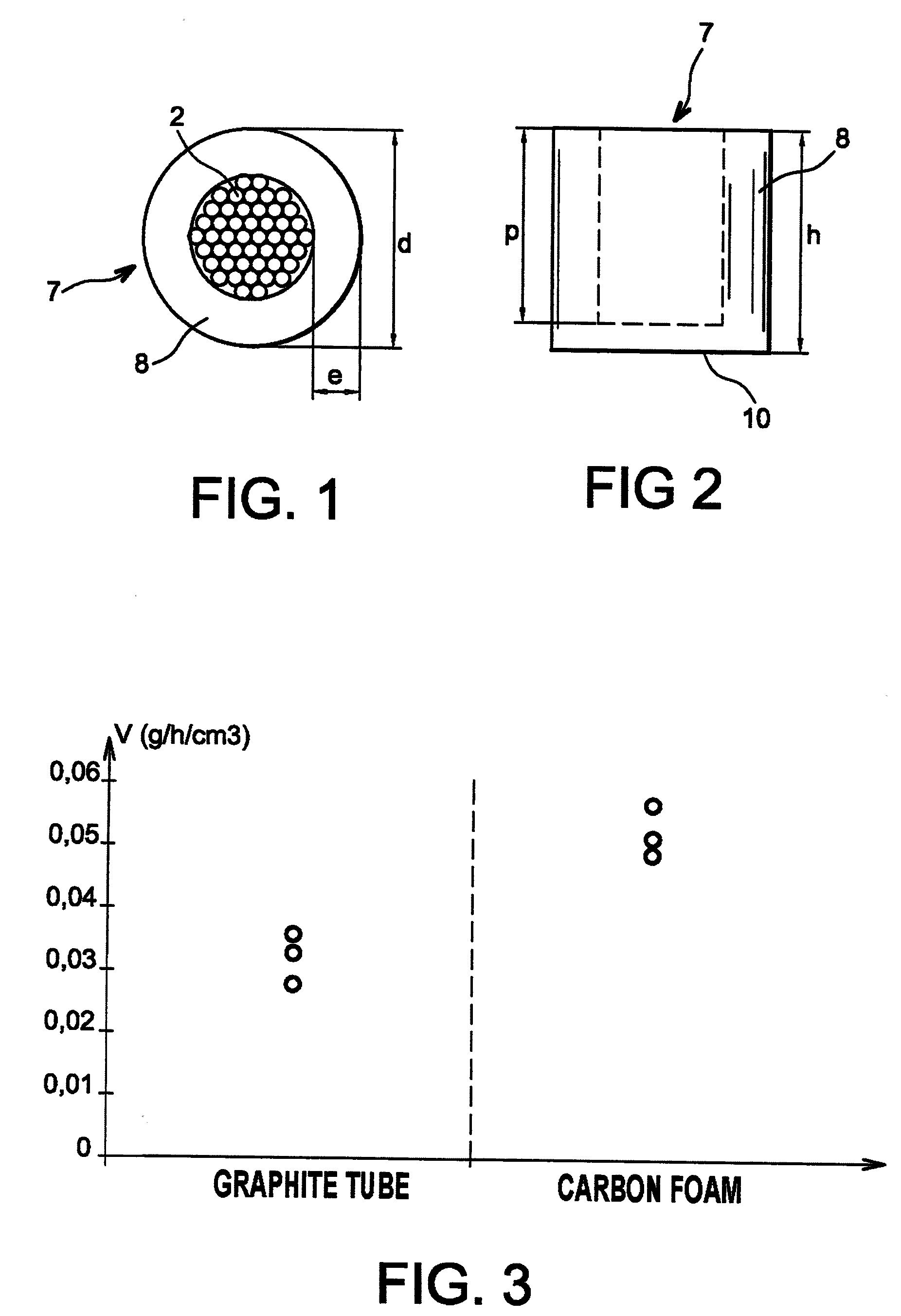
[0040]To this end, the container is produced from ultra-porous material, in particular a container made from graphite foam in which the balls are disposed in order to undergo chemical vapour densification. The porous structure of the container allows three-dimensional infiltration of the gaseous mixture. Thus the entire surface of the stack of balls is exposed to the gaseous mixture. Access of the precursors to the centre of the stack of balls is facilitated and the densification is made more homogeneous and higher.
[0042]In other words, there is provided a container able to allow the gaseous mixture to pass in three directions in space, in particular silicon carbide, and able to hold the balls in a given form. Thus the gaseous mixture is deposited evenly on the nuclear fuel balls. In this way a preferential densification direction and the appearance of heterogeneous densification are avoided.

Problems solved by technology

In the case of a container formed by a dense tube of the graphite tube type, the infiltration takes place solely in one direction, causing heterogeneous densification.

Method used


Image

  • Method of manufacturing nuclear fuel elements and a container for implementing such a method
  • Method of manufacturing nuclear fuel elements and a container for implementing such a method
  • Method of manufacturing nuclear fuel elements and a container for implementing such a method

Examples


Embodiment Construction

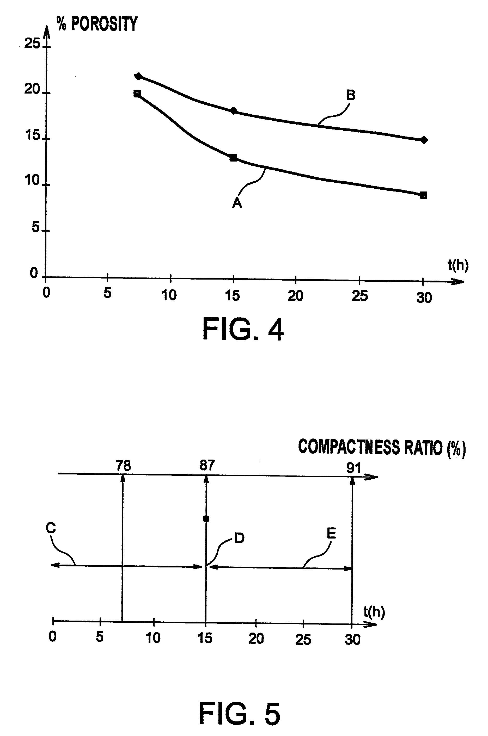
[0074]In order to show the effectiveness of the method according to the invention and of the container according to the invention, the following description will present the results of a method according to the present invention and those of a method using a container made from dense graphite.

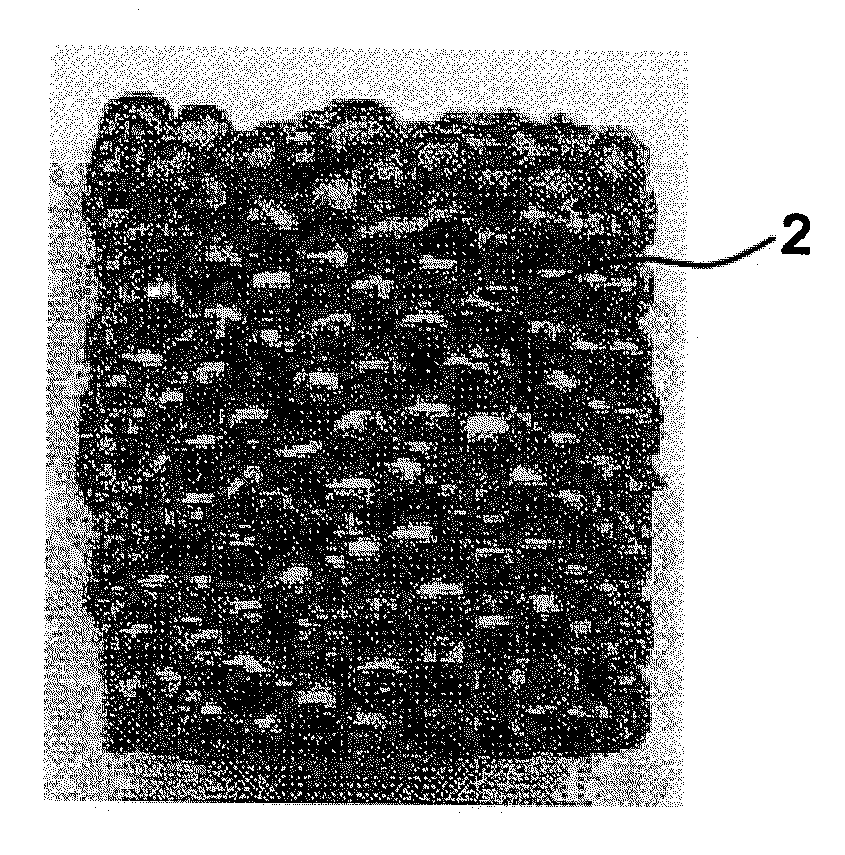
[0075]In FIG. 7, a nuclear fuel element can be seen obtained by the method according to the present invention comprising ceramic nuclear fuel balls 2, for example made from uranium oxide, embedded in a matrix 4 holding together the balls so as to form a self-supporting element.

[0076]The balls can have all substantially the same diameter, for example 1.2 mm.

[0077]Advantageously, it can be envisaged using balls with different diameters, for example two diameters with a ratio of 10 between the two. This has the advantage of making it possible obtain a high density, the balls of the smaller diameter filling in the free spaces between the balls with the larger diameter.

[0078]The nuclear fuel balls c...


PUM

PropertyMeasurementUnit
temperatureaaaaaaaaaa
porosityaaaaaaaaaa
thicknessaaaaaaaaaa

Abstract

A method of manufacturing nuclear fuel elements comprising the steps of placing nuclear fuel balls in the container made from ultra-porous material, applying a CVI to the container and removing the container. The container for manufacturing fuel elements comprising balls, and is produced from at least one ultra-porous material, for example carbon foam.

Description

TECHNICAL FIELD AND PRIOR ART[0001]The present invention relates to a method of manufacturing nuclear fuel elements, to a container for implementing such a method and to the elements obtained from such a method.[0002]This fuel, referred to as new generation, participates in the development of new designs of reactors, known as fourth generation.[0003]More particularly, the invention concerned is a method of manufacturing fuel elements in the form of a three-dimensional composite object comprising a stack of spherical ceramic particles, for example with the same diameter (monomode distribution) dispersed in a matrix produced by a chemical gas deposition, in particular by a chemical vapour infiltration (CVI) method.[0004]In the context of the development of new designs f reactors, known as fourth generation, a new type of installation is envisaged, functioning in a high temperature range—the temperature of the cooling fluid emerging from the reactor is above 800° C.—with a rapid neutro...

Claims


Application Information

Patent Timeline
Patent Type & Authority Applications(United States)
IPC IPC(8): G21C3/62G21C3/26G21C21/02C23C16/00B05C13/00
CPCG21C3/28G21C3/62G21C3/626G21C21/02Y02E30/38G21Y2002/202G21Y2002/304G21Y2004/40G21Y2002/10C04B35/51C04B35/5158C04B35/573C04B41/009C04B41/4529C04B41/87C04B2111/00862C04B2235/3826C04B2235/483C04B2235/528C04B2235/5427C04B2235/614C04B2235/6587C04B2235/77C04B2235/80Y02E30/30C04B41/4933C04B41/5059G21C3/26
Inventor BROLI, JEROMEGOYHENECHE, JEAN-MARCMAZAUDIER, FABRICELANGLAIS, FRANCIS
Owner COMMISSARIAT A LENERGIE ATOMIQUE ET AUX ENERGIES ALTERNATIVES
Learn More