
Brake operation built-in test equipment

a test equipment and brake technology, applied in the field of brakes, can solve problems such as abnormal operation of brakes, and abnormal operation of brake systems

Inactive Publication Date: 2010-11-18
THE BF GOODRICH CO
View PDF18 Cites 68 Cited by
  • Summary
  • Abstract
  • Description
  • Claims
  • Application Information

AI Technical Summary

Benefits of technology

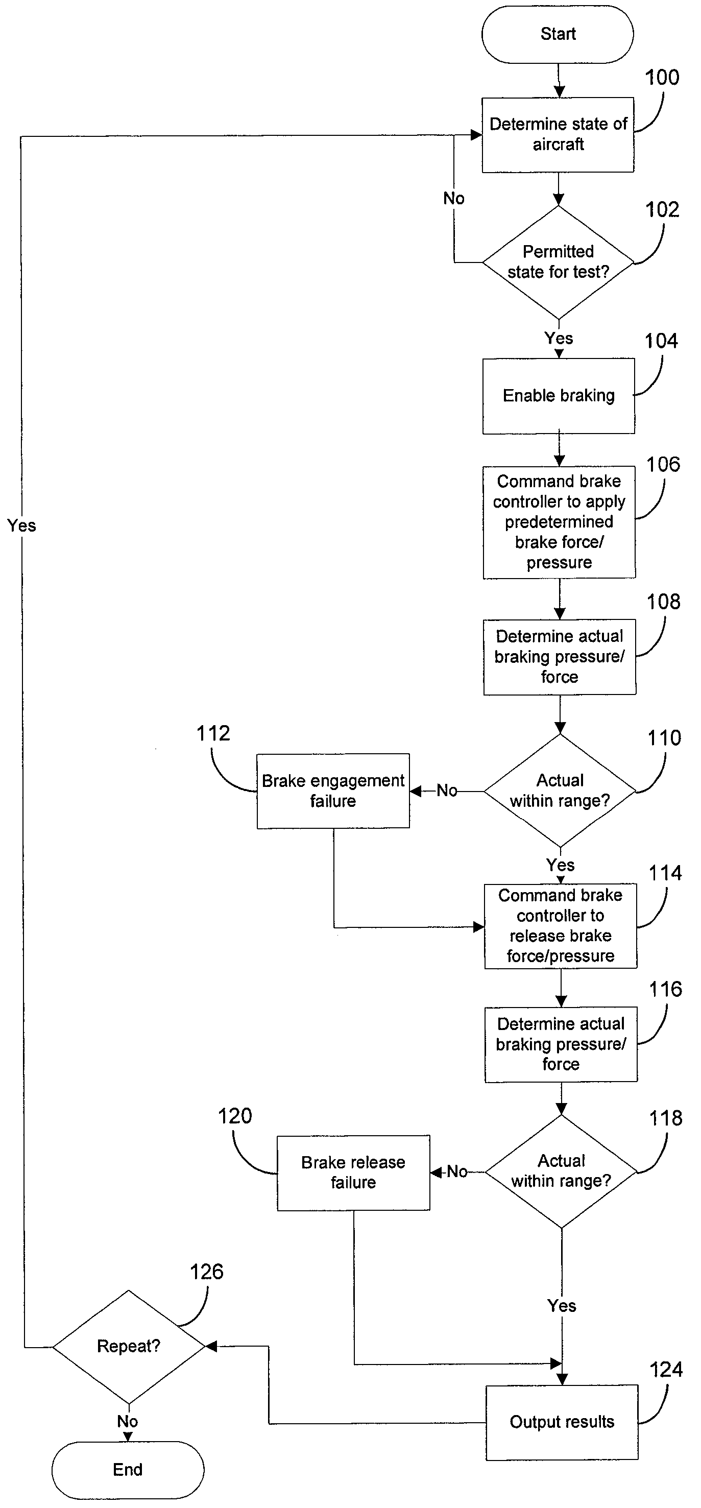
[0008]In one embodiment, one or more operational phases of the aircraft is/are determined, and the brake actuator is commanded to engage the brake-disk stack only when the operational phase corresponds to a predetermined operational phase. Additionally, the brake-disk stack can be commanded to release the brake-disk stack after the engagement force is determined. Then a residual force applied to the brake-disk stack is determined, and the residual force is compared to a release criteria. If the residual force is within a predetermined range of the release criteria, it is concluded that the brake system is operating normally, otherwise is concluded that the brake system is operating abnormally. The results of each comparison can be output and/or logged.
[0009]In another embodiment, an event corresponding to at least one of a brake command initiated via a brake input device, a wheel not at zero speed, or weight on the wheels is detected. If such event is detected, then the test is inhibited. Further, the test can be enabled when a landing gear handle or a gear down lock sensor transitions from a landing gear up position to a landing gear down position, and other disabling criteria are not present.
[0010]According to another embodiment, the testing device includes a first output for providing a command to the actuator, and a first input for receiving da...

Problems solved by technology

If the determined braking force is not within the acceptable range, then it is concluded that the brakes are operating abnormally.
If the residual force is within a predetermined range of the release criteria, it is concluded that the brake system is operating normally, otherwise is concluded that the brake system is operating abnormally.

Method used


Image

  • Brake operation built-in test equipment
  • Brake operation built-in test equipment
  • Brake operation built-in test equipment

Examples


Embodiment Construction

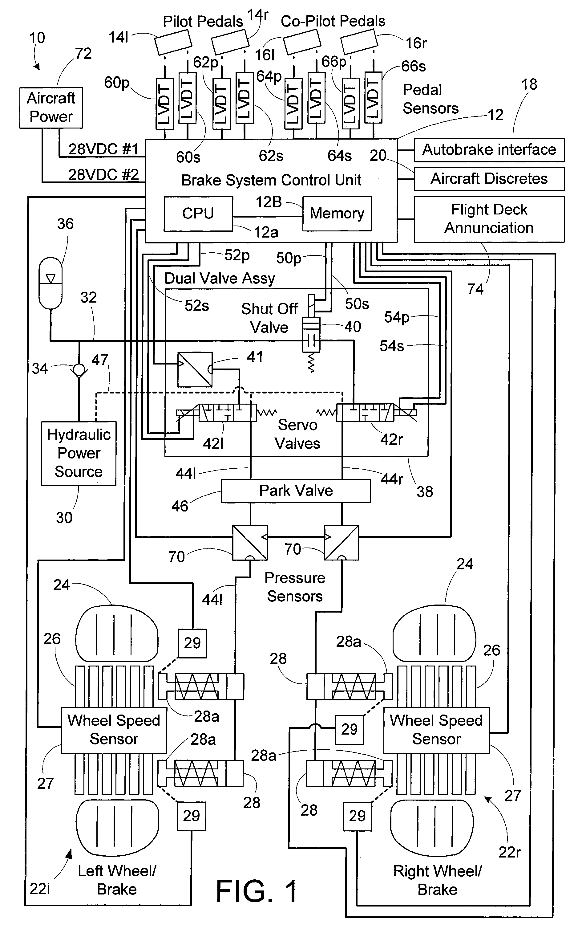
[0018]The principles of the invention will now be described with reference to the drawings. Because the invention was conceived and developed for use in an aircraft braking system, it will be herein described chiefly in this context. However, the principles of the invention in their broader aspects can be adapted to other types of braking systems on other types of vehicles.

[0019]A system, apparatus and method in accordance with the present invention enable vehicle brakes, such as brakes of an aircraft, to be tested during normal use of the aircraft. Results of the test can be provided to the pilot and / or logged in a maintenance log for later analysis. In accordance with the present invention, the test includes one or more of the following steps: determining an operational phase of the aircraft (e.g., moving or stationary, in flight, landing, velocity, etc.); enabling the braking system; applying and / or releasing the brakes; determining a brake force applied by the brakes; comparing ...


PUM


Abstract

A system, apparatus and method provide a means for testing operation of vehicle brake system. More particularly, a brake actuator is automatically commanded to engage a brake disk stack while the vehicle is in a benign state. An engagement force applied to the brake-disk stack by the actuator then is determined, and the engagement force is compared to a first threshold value. If the engagement force is within a predetermined range of the first threshold value, it is concluded that the brake system is operating normally, otherwise it is concluded that the brake system is operating abnormally.

Description

FIELD OF THE INVENTION[0001]The present invention relates generally to brakes and, more particularly, to a method, apparatus, and system for testing operation of brakes.BACKGROUND[0002]Known in the prior art are aircraft wheel and brake assemblies including a non-rotatable wheel support, a wheel mounted to the wheel support for rotation, and a brake disk stack having front and rear axial ends and alternating rotor and stator disks mounted with respect to the wheel support and wheel for relative axial movement. Each rotor disk is coupled to the wheel for rotation therewith and each stator disk is coupled to the wheel support against rotation. A back plate is located at the rear end of the disk pack and a brake head is located at the front end. The brake head houses a plurality of actuator rams that extend to compress the brake disk stack against the back plate. Torque is taken out by the stator disks through a static torque tube or the like.[0003]Operation of aircraft brake assemblie...

Claims


Application Information

Patent Timeline
IPC IPC(8): G06F19/00
CPCB60T8/1703B60T8/885B64F5/0045B64C25/42B60T2270/406B64F5/60B60T17/22B64C25/44F16D55/36
Inventor CAHILL, ERIC D.PRENTICE, DALE R.
Owner THE BF GOODRICH CO
Learn More