
Wind mill power flow control with dump load and power converter

a wind mill and power converter technology, applied in the direction of electric generator control, process and machine control, instruments, etc., can solve the problems of time-consuming restart of the generator, slow mechanical regulating system, and further increase of the speed of the rotor, so as to reduce the rate and fast reconnection of the wind mill

Inactive Publication Date: 2010-11-18
ABB POWER GRIDS SWITZERLAND AG +1
View PDF4 Cites 47 Cited by
  • Summary
  • Abstract
  • Description
  • Claims
  • Application Information

AI Technical Summary

Benefits of technology

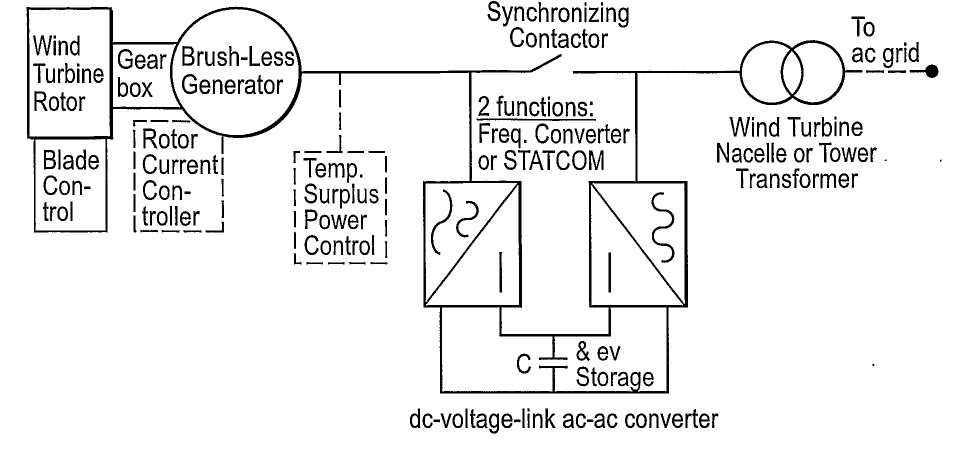
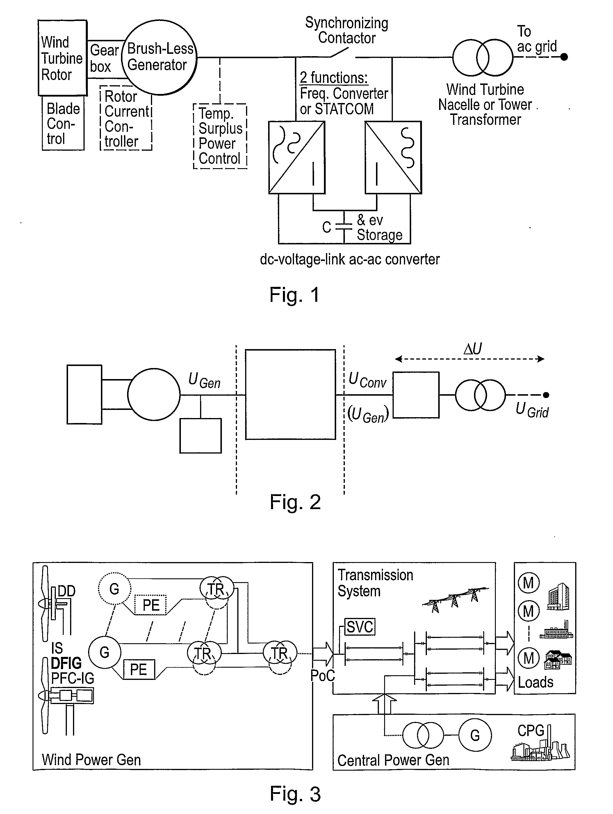
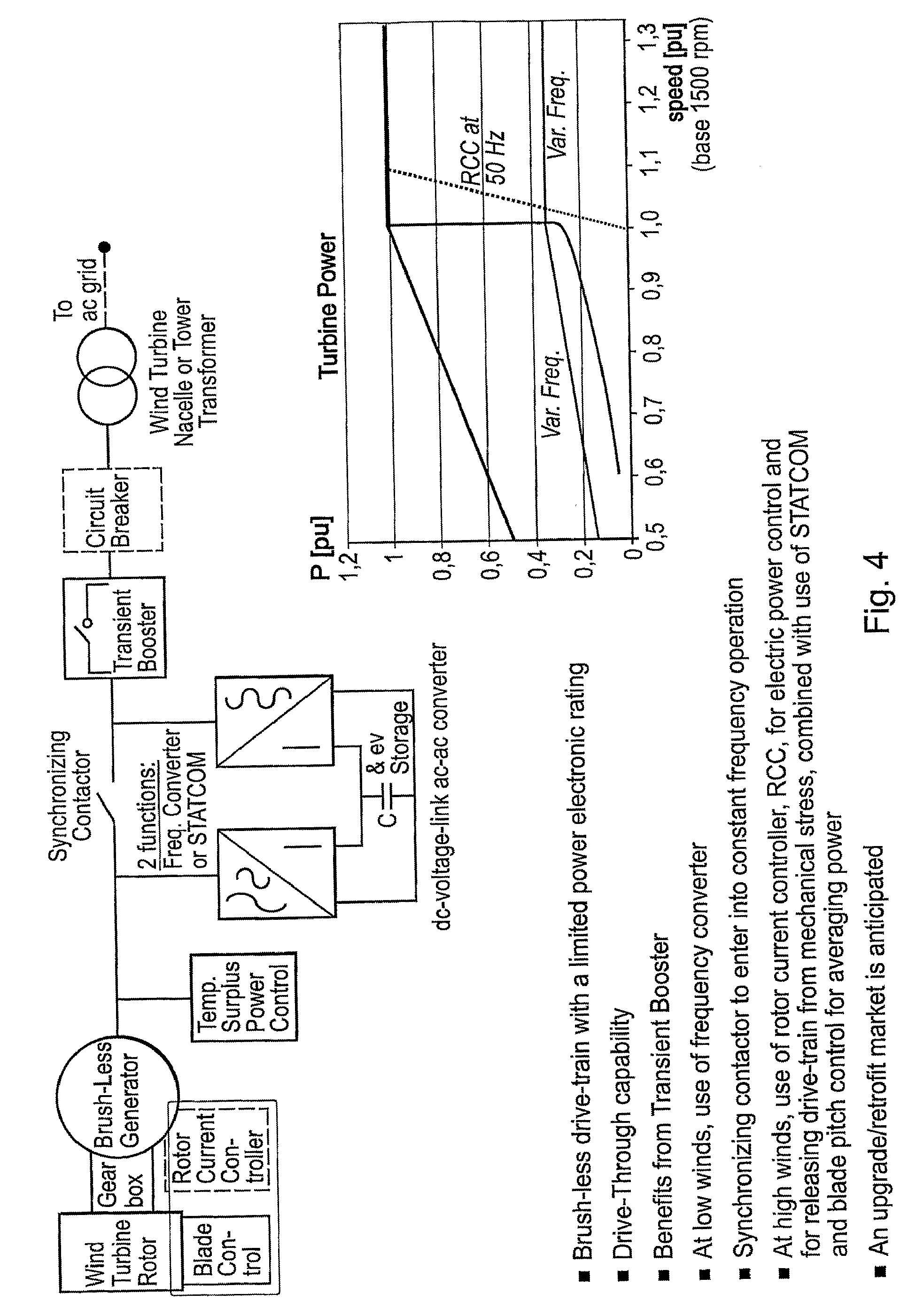
[0013]According to the invention an electric energy consumer, a dump load, is introduced between the generator and the grid point. The dump load is intended for consuming energy from the rotor system of the wind mill apparatus when the wind mill experience a fault situation in the grid point. By connecting such a dump load in a fault situation the passage of reactive energy is stopped while still active energy may pass at a reduced rate. The dump load is also direct connected to the generator and will thus provide a smooth retardation force to the generator and the whole rotating system. The dump load will keep the voltage in the wind mill circuit at a high level thus preventing switchgear apparatus to disconnect the wind mill from the grid point. By using such a dump load the synchronization with the grid point will be kept thus providing a fast reconnection of the wind mill to the network when the fault condition has elapsed.

Problems solved by technology

On the other hand the wind mill looses the synchronization to the network which implies a time consuming restart of the generator.
A sudden disconnection of the generator from the network interrupts this force balance and the wind rotor starts free wheeling.
However these mechanical regulating systems are slow.
Due to time consuming regulation of the wings of the wind mill and due to the fact that the wind is still transferring wind energy to the wind mill the speed of the rotor is further increased.
By the time the rotor experience retardation from the mechanical regulation the rotor speed may already have reached hazardous levels.
However there is no control of the wind mill once it has been disconnected from the network.
Thus the synchronization is lost and therefore the wind mill has to be started from scratch.
This is time consuming and during this time the wind mill will not generate power to the network.

Method used


Image

  • Wind mill power flow control with dump load and power converter
  • Wind mill power flow control with dump load and power converter
  • Wind mill power flow control with dump load and power converter

Examples


Embodiment Construction

[0026]Among the technical area of power production by wind mills there are a plurality of needs to fulfill. A first need is; Cost-effective, highly available wind turbines form a main problem. It may shortly be expanded as: “brush-less generators close to motor standard” and “partly rated power electronic converters”. A second need is;

[0027]Avoiding wind power generation park disconnection during grid voltage dips. It may be expanded as: “to drive-through wind turbines at grid-faults” and “to release collection & transmission (C&T) grids from electrical stress”. This issue is under harmonization within the common market of EG but today under national grid codes. A third need is: Avoiding excessive mechanical drive-train stress in wind turbines during various normal operation as well as at grid faults is the third one. It may be expanded as “to release their drive-trains from mechanical stress due to high winds and / or three-phase or two-phase faults”.

[0028]The new brush-less method a...


PUM


Abstract

A wind mill apparatus for generating electric power to a grid point of an electric network. The apparatus includes a wind rotor, an electric generator operatively connected to the wind rotor, and an electric multiphase ac link operatively connecting the generator to the grid point. The ac link includes a first current path including a switchgear, a second current path including a dc link including a first converter operatively connected to the generator, a second converter operatively connected to the grid point, and a capacitor operatively connected between the conductors of the dc link. The ac link further includes a connectable multiphase dump load for blocking during a fault condition on the network the reactive power flow in the ac link, yet providing a reduced transfer of active power.

Description

TECHNICAL FIELD[0001]The present invention concerns an electric power generation system. Preferably the system comprises electric power generating means and a transmission line connected to a grid point of an electric power network. The network comprises a plurality of power consumers and other power generating units. The power consumers comprise preferably motors, furnaces and the like and may be represented by loads on the network. Especially the invention concerns a power generating system comprising a wind mill. Commonly a plurality of wind mills is assembled into wind mill parks. Such wind mill parks may contain up to a hundred wind mill units and are preferably located at sea. Typically a wind mill comprises a rotor with vanes connected to an electric generator via a gear box. The wind mill also contains electrical equipment, such as transformer and converters, and means for controlling the electric and mechanical equipment.BACKGROUND OF THE INVENTION[0002]From U.S. Pat. No. 7...

Claims


Application Information

Patent Timeline
IPC IPC(8): G06F1/30H02H7/06
CPCH02H7/067H02J3/1842Y02E10/763H02J3/386Y02E40/22H02J2300/28H02J3/381Y02E10/76Y02E40/20H02J3/40
Inventor GERTMAR, LARSCHRISTENSEN, HANS CHRISTIANNIELSEN, ERIK KOLBYNIIRANEN, JOUKOTHORBURN-JOHANSSON, STEFANWRAAE, LEIF-ERIK
Owner ABB POWER GRIDS SWITZERLAND AG
Learn More