Vehicle antenna system

a technology of vehicle antenna and antenna, applied in the direction of antenna details, digital transmission, antenna adaptation in movable bodies, etc., can solve the problems of high installation cost, difficult installation, difficult reception, etc., and achieve the effect of improving antenna reception performance and good reception of dtv radio waves

Inactive Publication Date: 2010-11-18
FUJITSU GENERAL LTD
View PDF3 Cites 7 Cited by
  • Summary
  • Abstract
  • Description
  • Claims
  • Application Information

AI Technical Summary

Benefits of technology

[0005]Therefore, the present invention has as its object to provide a cheap and easy-to-install vehicle antenna system providing on the front windshield of a vehicle exactly the minimum number of loop antennas changed in directivity so as to improve the reception directivity of DTV broadcasts and enable good reception of DTV broadcasts regardless of the orientation of the forward direction of the vehicle.
[0011]According to the vehicle antenna system of the present invention, the directivity of the plurality of loop antennas set on the front windshield of the vehicle is not limited to the vehicle length direction, but it is also in the width direction of the vehicle, so even if the forward direction of the vehicle changes, good reception of DTV radio waves is possible and therefore antenna reception performance is improved.

Problems solved by technology

However, a conventional loop antenna attached at the top of a front windshield to receive DTV broadcasts had directivity toward the vehicle front, so there was the problem that reception became difficult when the vehicle changed directions.
However, this antenna diversity system requires circuitry for switching antennas, circuitry for combining received radio waves, and other circuitry.
Further, installation was difficult and the installation costs were high.

Method used


Image

  • Vehicle antenna system
  • Vehicle antenna system
  • Vehicle antenna system

Examples


first embodiment

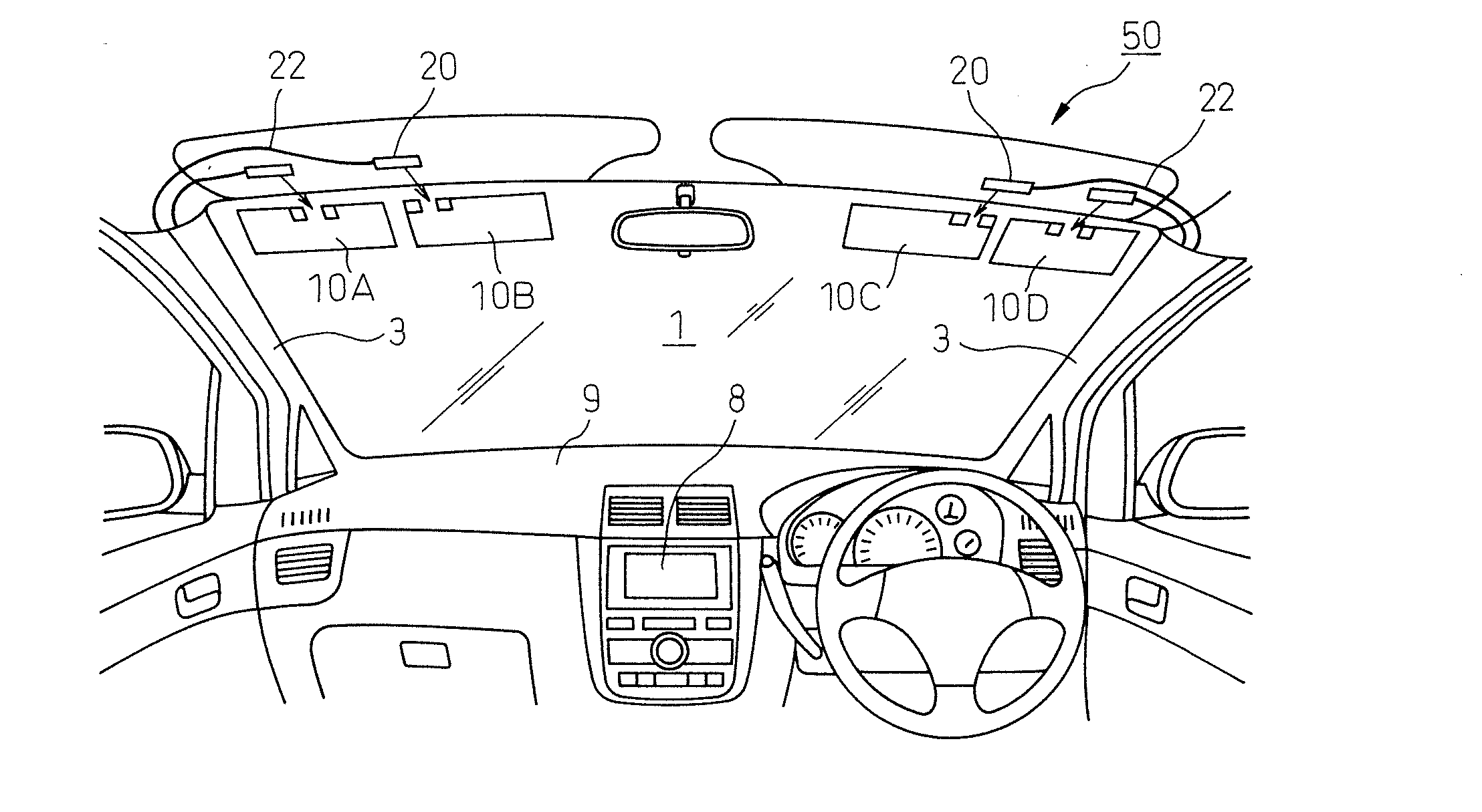
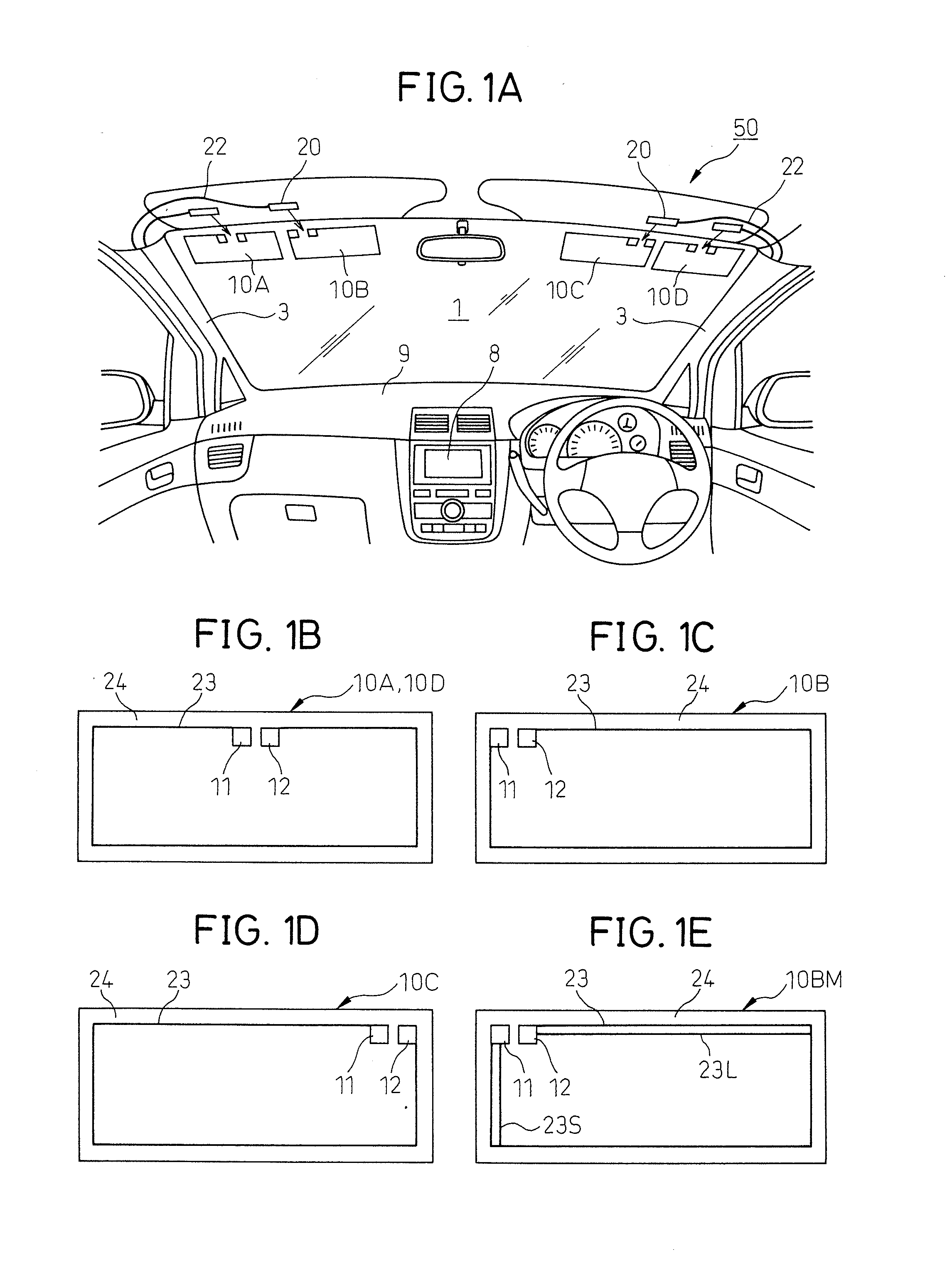
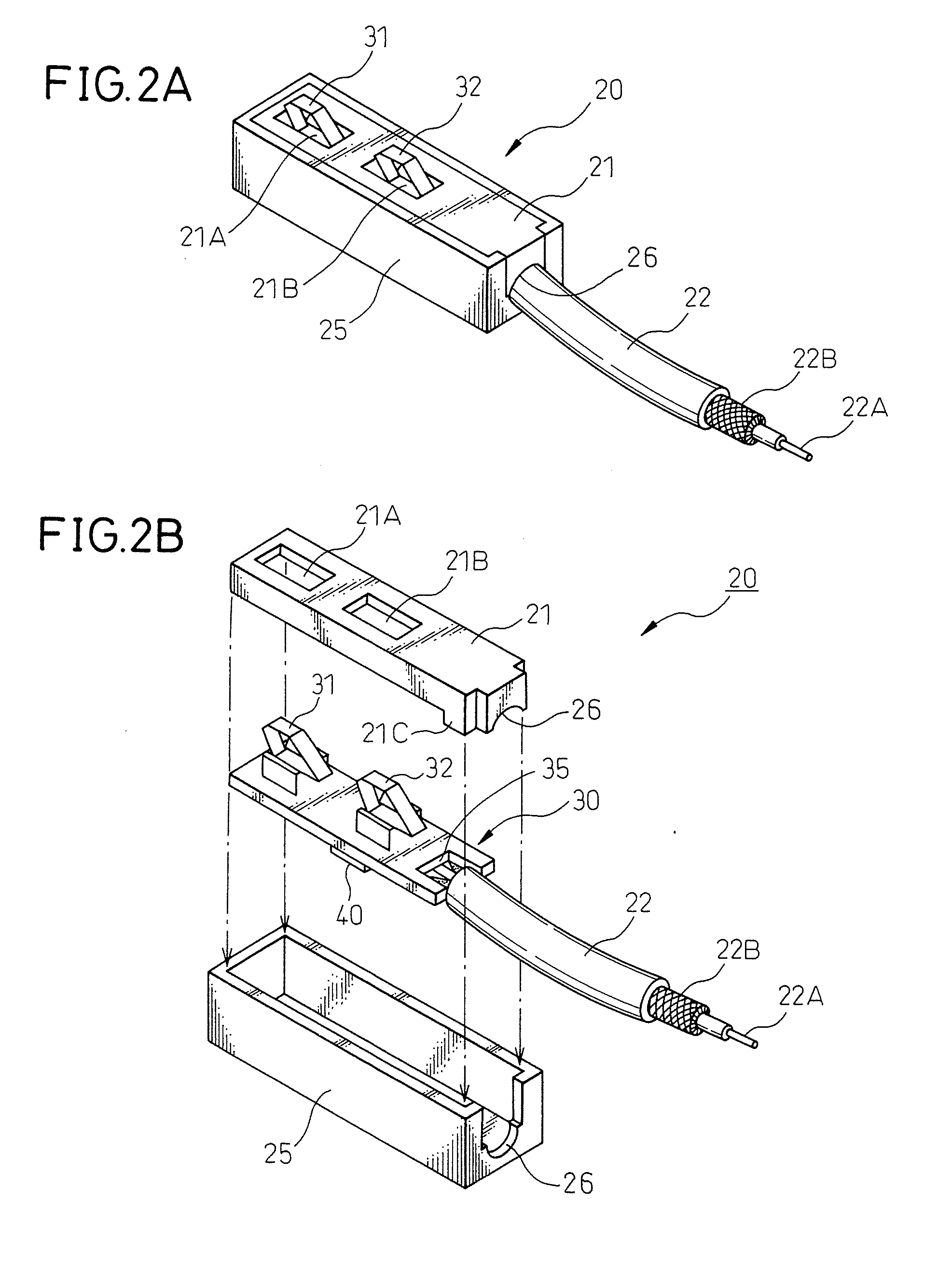
[0045]FIG. 1A shows the structure of a vehicle antenna system 50 according to the present invention attached to the top of the left and right of a front windshield 1 of an automobile. It shows the front windshield 1 of the automobile and the surroundings of the same from the vehicle interior. The antenna system 50 of this embodiment is for receiving a DTV broadcast and comprises four film antennas 10A, 10B, 10C, and 10D. The four film antennas 10A, 10B, 10C, and 10D are each connected to a feed circuit comprised of a connector 20 and coaxial cable 22.

[0046]The signals that are received by the film antennas 10A, 10B, 10C, and 10D are input into the feed circuits provided with the coaxial cables 22 through the connectors 20. The coaxial cables 22 are situated along the A pillars 3 of the automobile and connected to a digital TV tuner not shown in the drawing. Reference notation 8 is a car navigation system set in the instrument panel 9 of the automobile. This receives image signals fr...

second embodiment

[0068]In the antenna system 50 of the second embodiment, compared with the directivity of the film antennas 10C and 10B explained with reference to FIGS. 6A and 6C, the directivity of the antenna system 50 in the vertical direction when the automobile 60 is seen from the side is closer to vertical as shown in FIG. 8. As a result, the radio waves of the DTV broadcast from the rear of the automobile 60 become easier to receive and the reception performance of the antenna system 50 is improved. Note that, the directivity shown by the broken line shows the approximate direction of the directivity and is not an accurate depiction of the directivity.

[0069]FIG. 7B is a view of only the front windshield 1 of the automobile, seen from the vehicle interior, showing the structure of a modification of the vehicle antenna system 50 shown in FIG. 7A. In this embodiment, in place of the film antennas 10C and 10B explained in FIG. 7A, film antennas 10E and 1OF provided with parasitic elements 16 ar...


PUM


Abstract

A system improving reception performance of a terrestrial digital broadcast loop antenna attached to the front windshield of a vehicle, provided with at least one loop antenna with directivity in a direction parallel to the vehicle length direction and at least two loop antennas with directivity in a direction away from a direction parallel to the vehicle length direction, wherein these loop antennas are all set near conductors that make up the vehicle. The loop antenna with directivity in a direction parallel to the length direction of the vehicle is, viewed from a vehicle interior, set near the top left-right vicinity of the front window, while the two loop antennas with directivity in a direction away from the direction parallel to the vehicle length direction are positioned adjacent to this loop antenna.

Description

TECHNICAL FIELD[0001]The present invention relates to a vehicle antenna system. The present invention particularly relates to a vehicle antenna system comprising a plurality of loop antennas attached to parts around a front windshield of a vehicle.BACKGROUND ART[0002]In the past, automobiles and other vehicles have been equipped with antennas enabling the reception of radio waves even during movement. The radio waves received by a vehicle for many years have principally been the medium waves (MW) for AM radio and the very high frequency (VHF) or ultrahigh frequency (UHF) waves for FM radio or television. However, in recent years, antennas for global positioning systems (GPS), antennas receiving digital terrestrial broadcasts, and other antennas receiving high frequency band radio waves have also been mounted in vehicles. Digital terrestrial TV hereon will be referred to as “DTV”.[0003]When attaching these antennas on a moving body, that is, a vehicle, the locations where the antenna...

Claims


Application Information

Patent Timeline
Patent Type & Authority Applications(United States)
IPC IPC(8): H01Q1/32
CPCH04L12/4633H04L12/4658H04L12/4662H04L45/68H04L45/50H04L45/66H04L45/00
Inventor OGINO, KAZUSHIGE
Owner FUJITSU GENERAL LTD
Why Eureka
Try Eureka