
Basketball return apparatus with track extender and deflector

a return apparatus and basketball technology, applied in the field of basketball training devices, can solve the problems of unintended removal, high device cost, and large size of the return apparatus, and achieve the effect of preventing unintended removal

Active Publication Date: 2010-11-11
WARES JONATHAN G
View PDF51 Cites 10 Cited by
  • Summary
  • Abstract
  • Description
  • Claims
  • Application Information

AI Technical Summary

Benefits of technology

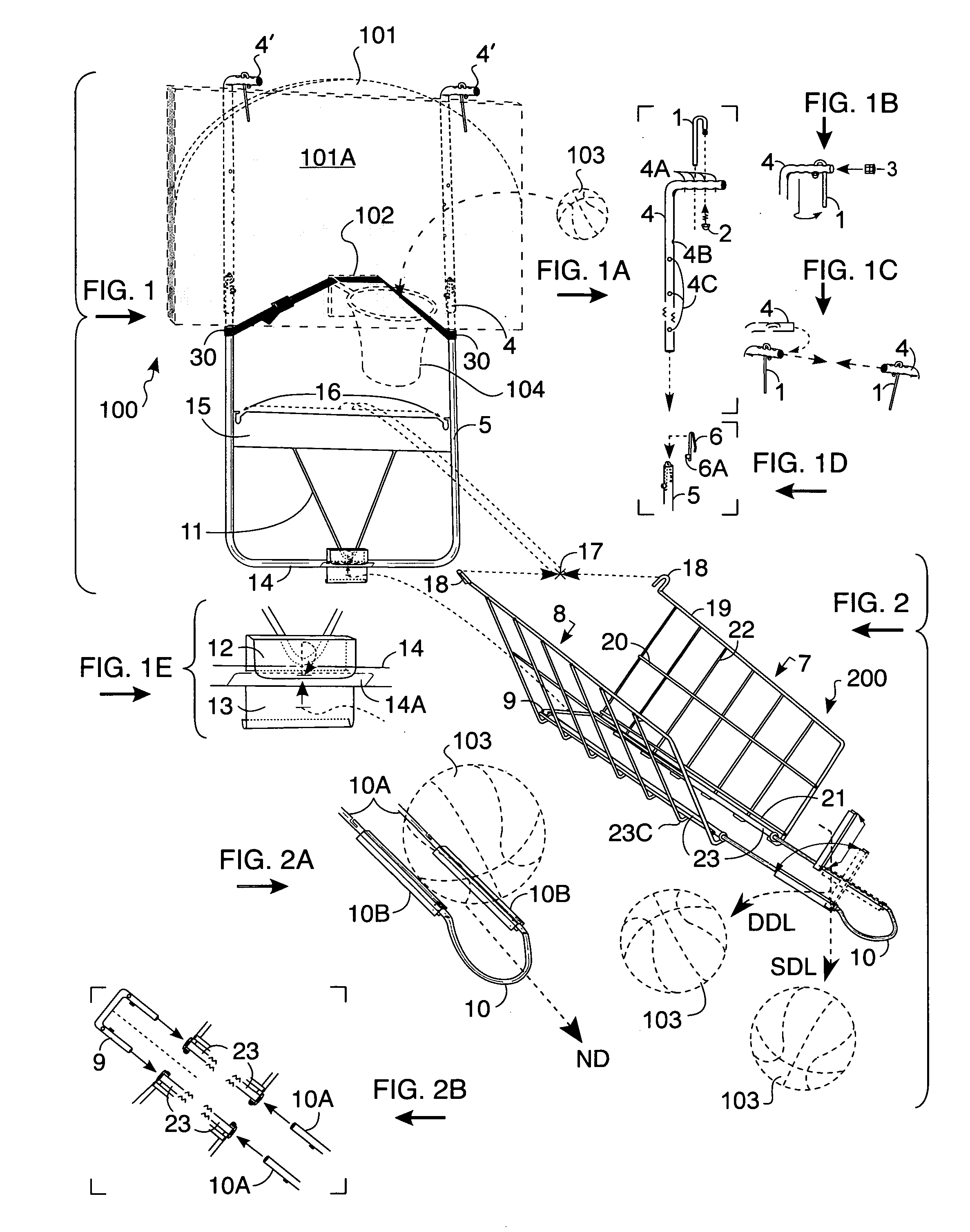
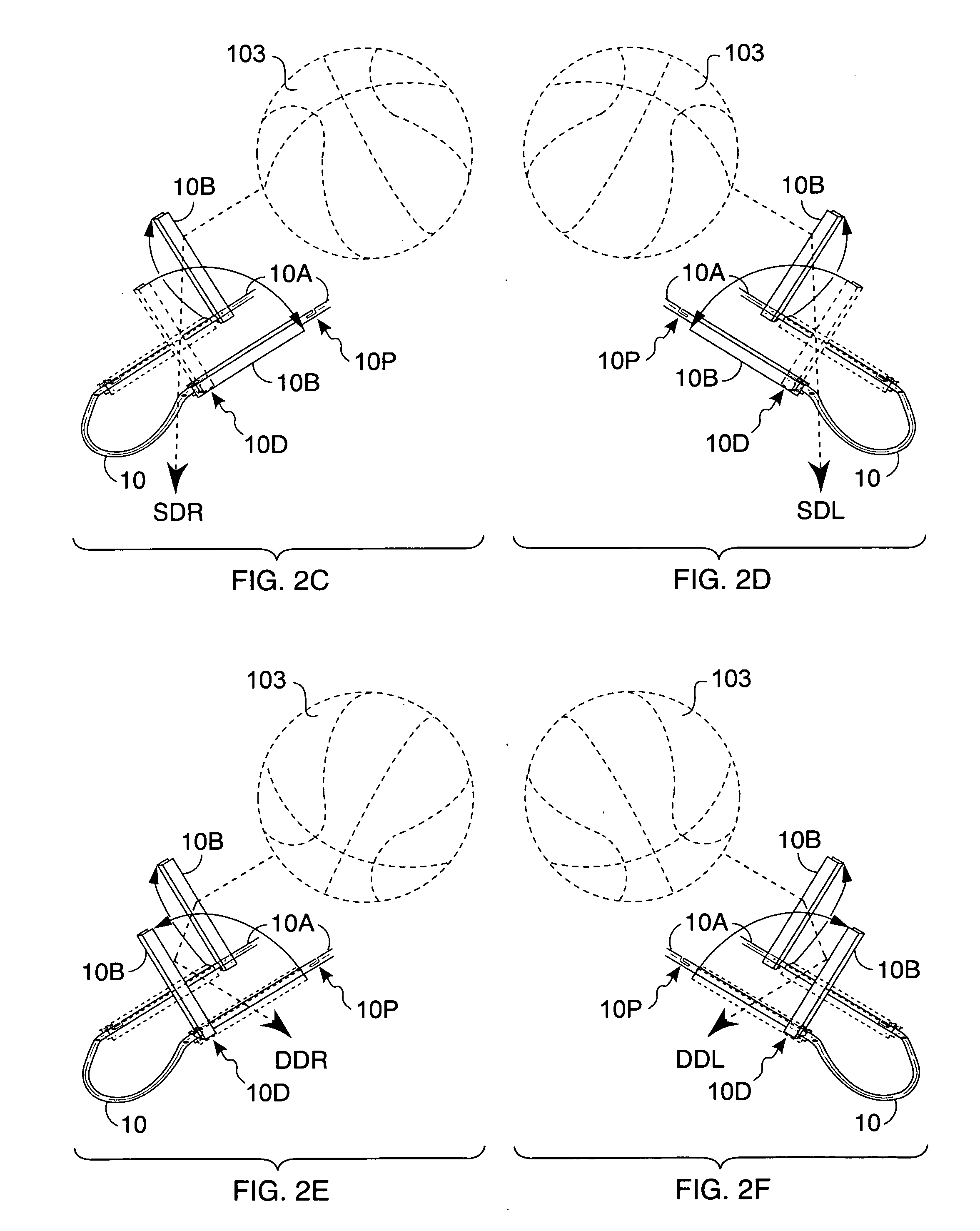
[0019]It is therefore an object of the present invention to provide a basketball retrieving apparatus which can be adjusted to be easily mounted and demounted from a conventional basketball backboard, regardless of the thickness of the backboard including any thickness added by the goal support assembly to which the backboard is mounted. It is further an object to provide a ball retriever apparatus adaptable to backboards varying in their vertical dimension. Further still, it is an object to provide a ball retriever which can be characterized in that the hoop and net of the goal assembly on which it is mounted is free from any and all encumbrances by the retriever apparatus, thereby ensuring the hoop and net being free to respond normally to the impact of the ball and presenting, for and during optimal use of the retriever, a substantially clear viewing path to the hoop and net from locations on-court circumscribed by a 180° arc in front of and alongside the backboard. Further, it is an object to provide a ball retriever apparatus with rigid ball collection and return means which guide a ball, including a missed shot entering said return in front of the goal, speedily downward by means of an extensible track which redeposits the basketball on a vigorous bounce to a player for a variable range of different locations. Further still, it is an object to provide a ball retriever apparatus with alternative, left and right court oriented track extender deflectors which can deliver the ball to other positions on court than those at a point perpendicular to and in the front and center of the goal. Also it is an object to provide a ball retriever which can allow players to stand beneath it close to the hoop to set up for practicing hook shots after receiving the ball directly from the apparatus. Further still, it is an object to provide a ball retriever apparatus designed for ease of assembly, adjustment, attachment, and detachment. The retriever apparatus is constructed so that it may be readily set up for use and as readily broken down and nested for transportation in which significant parts are hinged or telescoped together so that they may be folded and compressed into a compact substantially flat package for transport.
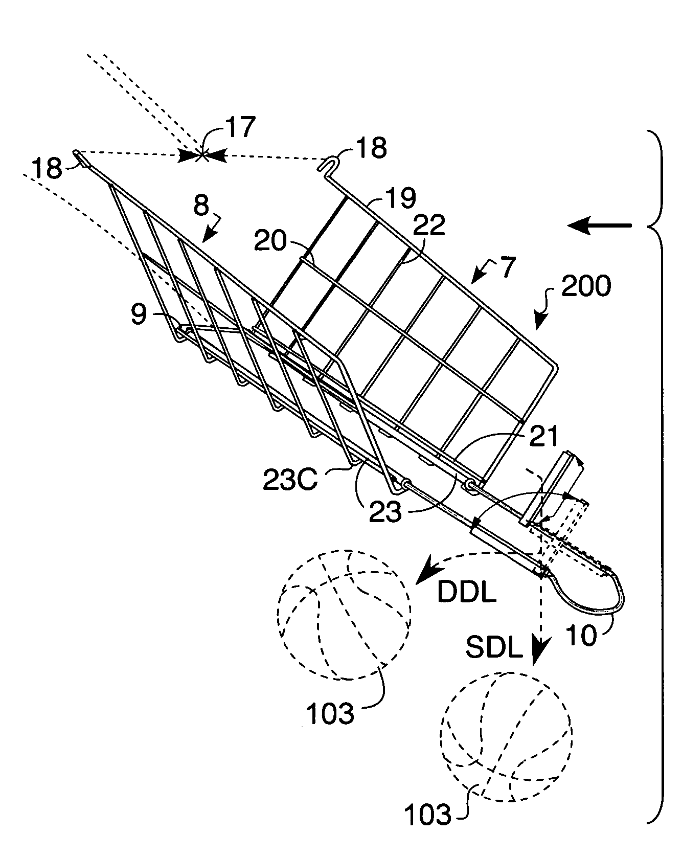
[0025]The extender can be adjustably connected to the rails to allow for various positioning of the extender with respect to the trough. In a particular embodiment, the extender comprises holding means for securing the extender to the rails and substantially preventing unintended removal of the extender during usage or carriage. Each deflector defines a proximal end and a distal end. Each deflector can be positioned substantially perpendicular to the axis of the rail at either the proximal or distal end. In a further embodiment, a reverse mounting belt or cord is attached to the lower frame member and lies over the hoop to provide additional structural support for the support assembly when the support assembly is mounted in reverse, back side of the backboard position.
[0026]In a particular embodiment, the panels are wires joined together to form each panel. In a further embodiment, some of the wires in the panels are parallel to the axis of the rails and are joined together by other vertically oriented wires which are connected to each of the rail means on an inside portion of the panel. The trough can be disconnected from the support assembly and folded flat for substantially compact carriage and storage. The extender is typically rounded at a distal end and angled down to provide the user with an ergonomically compatible grip for manual extension or retraction adjustment to deliver the ball straight to a user when the deflectors are lying flush and parallel with the rails or to the right or left side when the deflectors are positioned substantially perpendicular to the axis of the rails. The frame members can be adjustable so that the vertical position of the trough relative to the floor and hoop can be varied. Typically, the upper and lower frame members telescope into each other. Pin means, for securing the upper and lower frame members to each other, are adapted to pass through aligned holes defined in each of the frame members for adjusting the height of the lower frame members relative to the floor and hoop. In an even further embodiment, the holding means are adjustable so that the angle of the slope of the trough relative to the floor and hoop can be varied.

Problems solved by technology

There are problems because of the limitation imposed by the apparatus requiring an external power supply, not easily accessible indoors without additional equipment such as power extension cables with the appropriate type of plug for an available electrical outlet, and typically useless outdoors where such outlets are normally unavailable without provision of additional equipment such as a gas-powered electrical generator and fuel to power it.
Without use of a truck, users have the added problems of how to transport and where to store such a large type of apparatus when not in use.
The device is also expensive.
As with other apparatus of the type which depend from the hoop, there are problems with the deviation in the regulation size foramen of the hoop as a consequence of attachment of the apparatus's hooking members.
No longer are users assured that the encumbered goal assembly will respond in a normal manner to the impact of a ball striking it.
Yet another problem is that, even when attached to the backboard, the user's view of the hoop and net is substantially obscured by the apparatus, again resulting in the goal assembly being significantly altered in its standard appearance as a regulation goal.
More significantly, users of the Spier device have a problem with the fixed lateral run such apparatus afford the ball whereby its momentum can deliver it with similar efficiency only to a fixed range of different positions on court.
While in position to utilize the apparatus near the goal, players find it impossible to take shots from positions progressively farther from the goal without equally progressive loss of the apparatus's efficiency returning the ball.
Thus, a player stepping back to shoot from a somewhat further position experiences increasingly inconvenient setting events in terms of the speed and height of the ball's delivery.
The Caveney apparatus also has problems with accommodability, enabling use only with a backboard of predetermined vertical and thickness dimension, and lacking ease of mountability on the variety of different popular backboards having various other measures of these dimensions particularly the goal support assemblies to which they are attached.
Another limitation of the Caveney apparatus is that the ball is deliverable only to a player on the straightaway from goal to foul line and positions on right and left court are without delivery service.
In addition, during normal use of the apparatus, with both side panels typically outfolded for free-throw shooting, a user desiring to practice shooting from substantially right or left court finds both his view and the ball's access path to the goal substantially limited.
Players, accustomed to receiving the ball in the course of the game on a vigorous bounce, have a problem with the setting event of receiving a ball on a roll because it causes an interruption of their shooting stance with each practice trial and never allow them to establish a shooting rhythm catching, aiming and shooting the ball.

Method used


Image

  • Basketball return apparatus with track extender and deflector
  • Basketball return apparatus with track extender and deflector
  • Basketball return apparatus with track extender and deflector

Examples


Embodiment Construction

[0044]All patents, patent applications, government publications, government regulations, and literature references cited in this specification are hereby incorporated herein by reference in their entirety. In case of conflict, the present description, including definitions, will control.

[0045]U.S. Pat. No. 4,869,502 to Wares discloses a lightweight portable apparatus for retrieving a basketball herein incorporated by reference in its entirety.

[0046]As shown in FIGS. 1-1 E, 2-2F, and 5A-5D, an exemplary basketball retriever apparatus comprises a support assembly 100 and a trough assembly 200, which can be made of metal, plastic, rubber, wood, or fiberglass. The support assembly 100 and trough 200 are adapted to mount on an exemplary backboard 101 and hoop 102 assembly. Backboard 101 defines a front face 101A and a reverse back side. In an exemplary embodiment, the upper part or upper end of support assembly 100 comprises a pair of identical upper arms or stanchions 4, also referred t...


PUM


Abstract

The present disclosure provides for a foldable, portable, apparatus for use as an operant conditioning basketball shooting practice aid by retrieving and returning shots at the hoop. The apparatus is comprised of a dismountable trough assembly depending from crossbar slots of a support assembly frame. The trough assembly includes ball collection panels each mounted on separated ball runway tubes or rails with the legs of a track extender-deflector inserted into the tubes. The deflectors are adapted to be configured for quick interchangeability from one configuration to another to deliver the ball to various locations to center or side court.

Description

CROSS-REFERENCE TO RELATED APPLICATIONS[0001]Not ApplicableSTATEMENT REGARDING FEDERALLY SPONSORED RESEARCH OR DEVELOPMENT[0002]Not ApplicableBACKGROUND OF THE INVENTION[0003](1) Field of the Invention[0004]The present invention relates generally to basketball training devices, especially to a basketball return apparatus for use by a player in practicing field goal and free-throw shooting to improve shooting accuracy ultimately measured by a player's scoring percentage and the ability to return the ball to various locations on the court.[0005](2) Description of Related Art[0006]Many, if not most basketball players prefer to remain at one position at a time on the court during shooting practice. This is not due to athletic indolence but is a result of rather sound judgment about what is required of performance setting events in order to learn reliable shooting habits.[0007]For a player's acquiring the motor skill of basketball shooting accuracy, what is required for most efficient re...

Claims


Application Information

Patent Timeline
Patent Type & Authority Applications(United States)
IPC IPC(8): A63B69/00
CPCA63B63/083A63B2243/0037A63B2063/001A63B69/0071
Inventor WARES, JONATHAN G.
Owner WARES JONATHAN G
Learn More