
Decoy holder

Inactive Publication Date: 2005-11-17
WADE B ERIC
View PDF22 Cites 11 Cited by
  • Summary
  • Abstract
  • Description
  • Claims
  • Application Information

AI Technical Summary

Benefits of technology

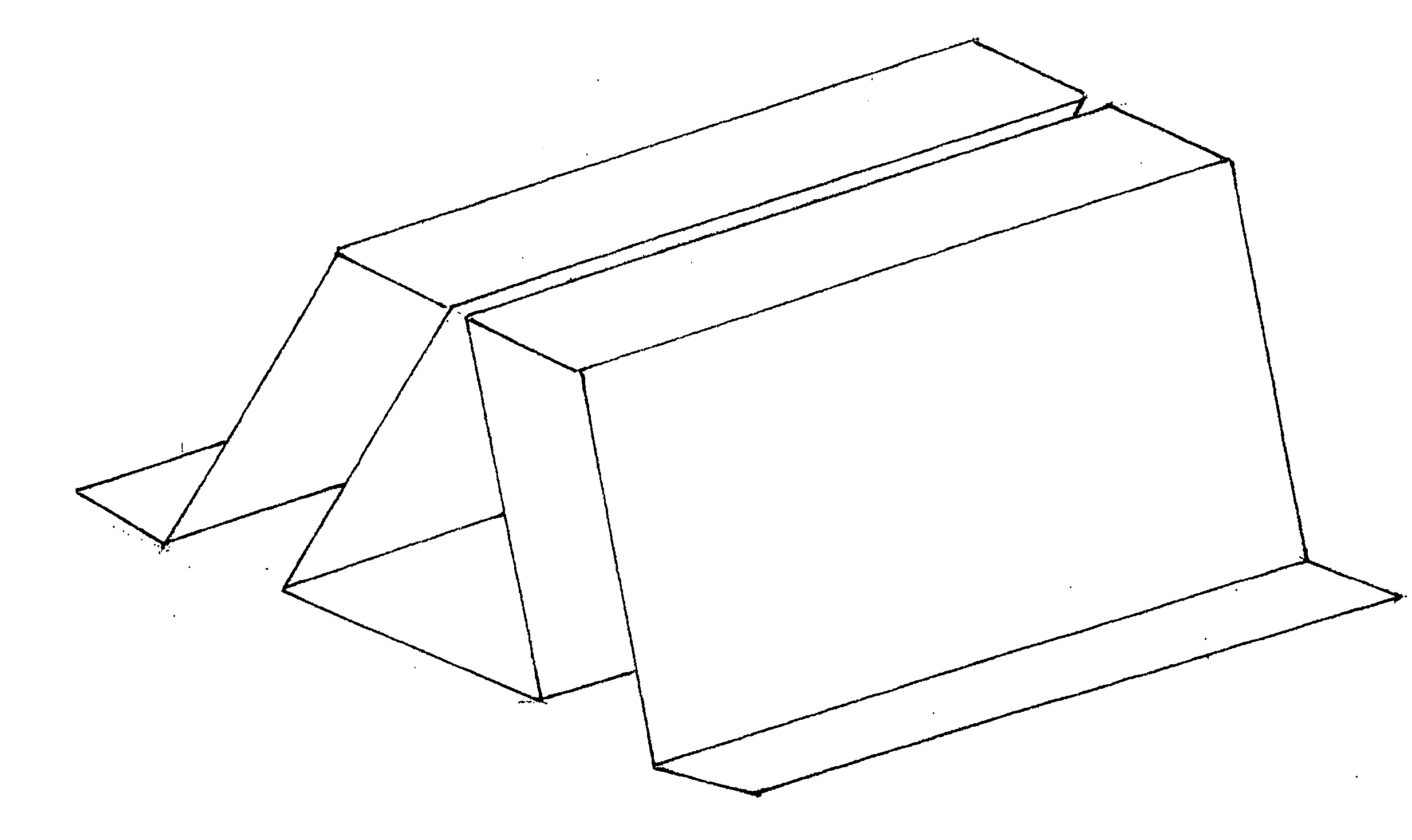
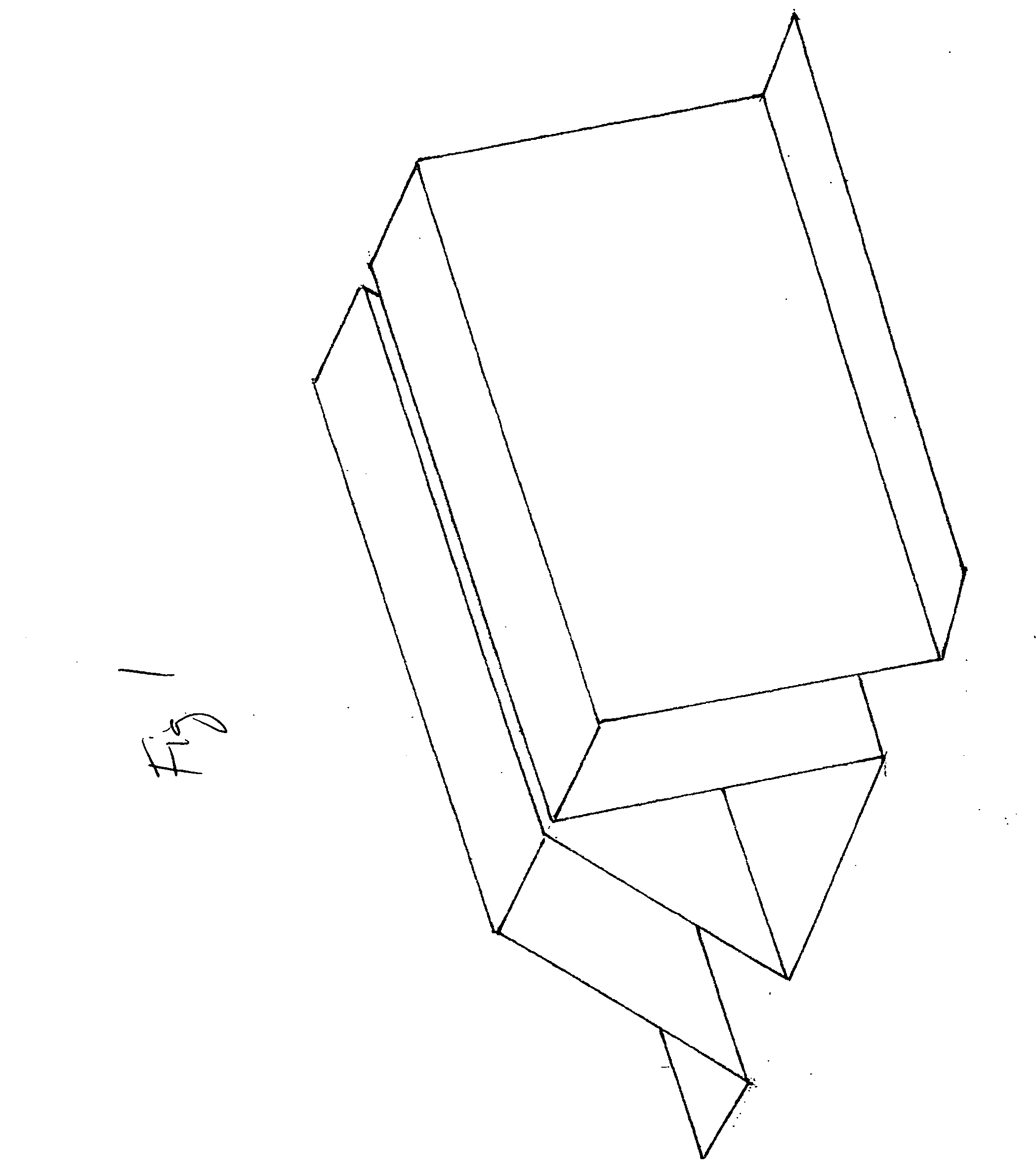
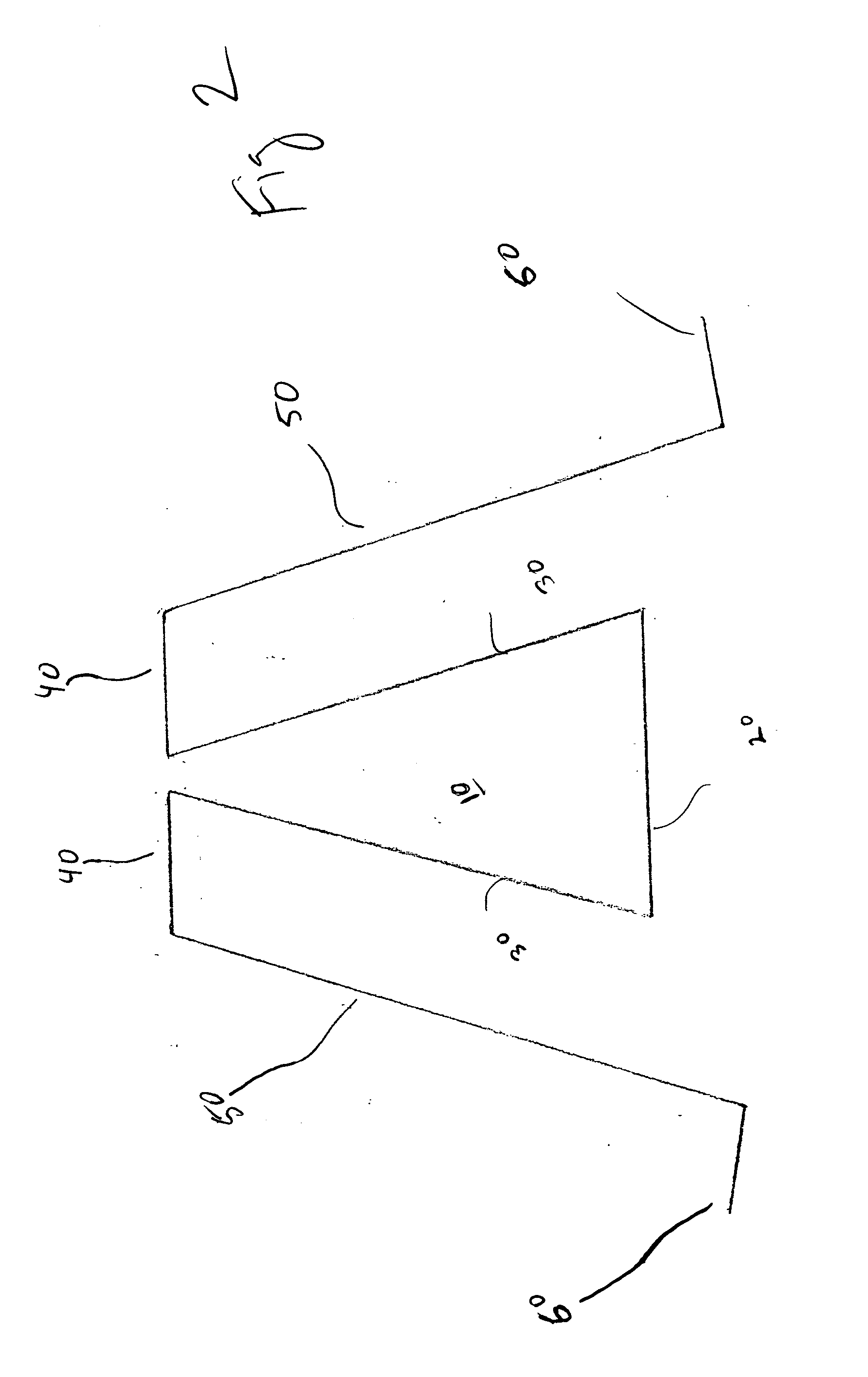
[0010] In a preferred embodiment, the holder is constructed as a single unit including a central cavity including a cavity base member, two sidewalls protruding upward from the base member, a generally flat top member extending from the top of each sidewall, a leg extending downward from each top member, and a generally flat foot extending from each leg. The feet support the decoy for which the keel has been inserted in the cavity in a generally upright position. The top members help to support the generally flat base of the decoy body located on either side of the keel.
[0011] In a preferred embodiment the holder is manufactured of a 24 gauge pre-finished metal which provides for suitable elastic deformation of the side walls of the central cavity to allow the keel to be easily inserted and removed from the central cavity. In addition, the elasticity of the metal causes the sides of the cavity to clamp around the keel and prevent accidental removal of the keel from the holder. The holder is manufactured by sequentially bending a flat sheet of the metal. For a 20 inch wide piece of metal, a first 80 degree bend is made approximately ¾ inches away from an end of the sheet of metal to form a first foot. A second 80 degree bend, is made in the opposite direction of the first bend approximately 4 inches from the first bend to form a first leg. A third 100 degree bend is then made in the same direction as the second bend approximately 1 inch away from the second bend to form a first top member. A fourth 100 degree bend is then made in the opposite direction as the third bend approximately 3¼ inches from the third bend to form a first cavity sidewall. A fifth 100 degree bend is made in the same direction as the fourth bend approximately 2 inches from the fourth bend to form the cavity base. A sixth 100 degree bend is made in the opposite direction as the fifth bend approximately 3¼ inches from the fifth bend to form a second cavity sidewall. A seventh 80 degree bend is made in the same direction as the sixth bend approximately 1 inch from the sixth bend to form a second top member. A final eighth bend is made in the opposite direction as the seventh bend approximately 4 inches from the seventh bend to form the second leg and foot.

Problems solved by technology

This can be extremely expensive and consumes considerable storage space.
Although some variations of shell decoys have been developed that float and can therefore be used for hunting over water, such decoys are not preferred by hunters because they are top heavy and therefore easily tip over in windy conditions.
The keel provides stability to the decoy while floating, but also makes use of the decoy on land impractical.
This is because the keel, which protrudes from the body, causes the decoy body the lay partially tipped over on the ground, resulting in an unrealistic appearance to the decoy.

Method used


Image

  • Decoy holder
  • Decoy holder
  • Decoy holder

Examples


Embodiment Construction

[0020] As required, a detailed embodiment of the present inventions is disclosed herein; however, it is to be understood that the disclosed embodiment is merely exemplary of the principles of the invention, which may be embodied in various forms. Therefore, specific structural and functional details disclosed herein are not to be interpreted as limiting, but merely as a basis for the claims and as a representative basis for teaching one skilled in the art to variously employ the present invention in virtually any appropriately detailed structure.

[0021] Referring to FIGS. 1-4, a preferred embodiment of the decoy holder of the instant invention is shown. In the preferred embodiment shown, the holder is constructed as a single unit including central cavity, 10, cavity base member 20, sidewalls 30 protruding upward from base member 20, generally flat top members 40 extending from the top of each sidewall 30, leg 50 extending downward from each top member 40, and generally flat feet 60 ...


PUM


Abstract

A decoy holder is provided that releasably retains the keel of a keel-type floater decoy. The holder includes a central cavity in which the keel of a decoy can be inserted. The holder includes a generally flat base that supports the decoy in an upright position on solid ground.

Description

[0001] This application claims priority pursuant to 35 U.S.C. 119(e) to co-pending U.S. Provisional Patent Application Ser. No. 60 / 567,560, filed May 3, 2004, the entire disclosure of which is incorporated herein by reference.FIELD OF THE INVENTION [0002] The present invention relates generally to decoys. More particularly, it is concerned with a holder or stand for supporting floating decoys on a solid surface and methods of supporting keel-type decoys. BACKGROUND OF THE INVENTION [0003] Animal decoys have been used for centuries for attracting various animals into the range of concealed hunters. The most recognized form of decoy is the duck or goose waterfowl decoy formed in three dimensions and painted to closely resemble the selected animal. [0004] Waterfowl can be found, and therefore are hunted, in a variety of different habits, including both water (i.e. marshes, ponds, lakes, rivers, ponds, etc.) and land. Therefore, three-dimensional waterfowl decoys have been developed for...

Claims


Application Information

Patent Timeline
IPC IPC(8): A01M31/06
CPCA01M31/06
Inventor WADE, B. ERIC
Owner WADE B ERIC
Learn More