
Gun equipped with camera

a technology of a gun and a camera, applied in the field of guns, can solve the problems of not providing a small amount of information, inflicting unnecessary pain, not disclosing, etc., and achieve the highest level of camera activity, enhance the camera activity, and enhance the level of activity

Inactive Publication Date: 2010-11-11
FRESSOLA ALFRED A +2
View PDF24 Cites 38 Cited by
  • Summary
  • Abstract
  • Description
  • Claims
  • Application Information

AI Technical Summary

Benefits of technology

"The present invention is a stun gun with a camera that can capture images and audio when the gun is unholstered or when its safety is released. The camera can automatically store the images and audio at full resolution, and the images can be deleted afterward to save storage space. The camera can capture images from both the target of the gun and the user of the gun. The camera can also capture audio and video from the user's perspective. The camera can be activated when the gun is unholstered or when its safety is released, and it can capture images continuously or at regular intervals. The camera can also be designed to delete or reduce the quality of the images to save storage space. The data storage is preferably implemented in the gun itself or in the holster with a link between the gun and the holster. Overall, the invention combines the stun gun with a camera to capture images and audio in a more efficient and effective way than previous inventions."

Problems solved by technology

A drawback to these types of prior art inventions is that merely recording a date and time, and / or discharging informational confetti, will only provide a slight amount of information about the circumstances in which a stun gun is used.
Another major problem with existing stun guns is that they can be misused so as to inflict unnecessary pain, or to unnecessarily incapacitate a target.
Additionally, Gotfried does not disclose any way to automatically activate a gun before a user places a finger on the trigger, during which time many significant events may be occurring in view of the gun.
Nevertheless, the VDPM does not address or solve any of the problems identified above with respect to the other prior art.

Method used


Image

  • Gun equipped with camera
  • Gun equipped with camera
  • Gun equipped with camera

Examples


Embodiment Construction

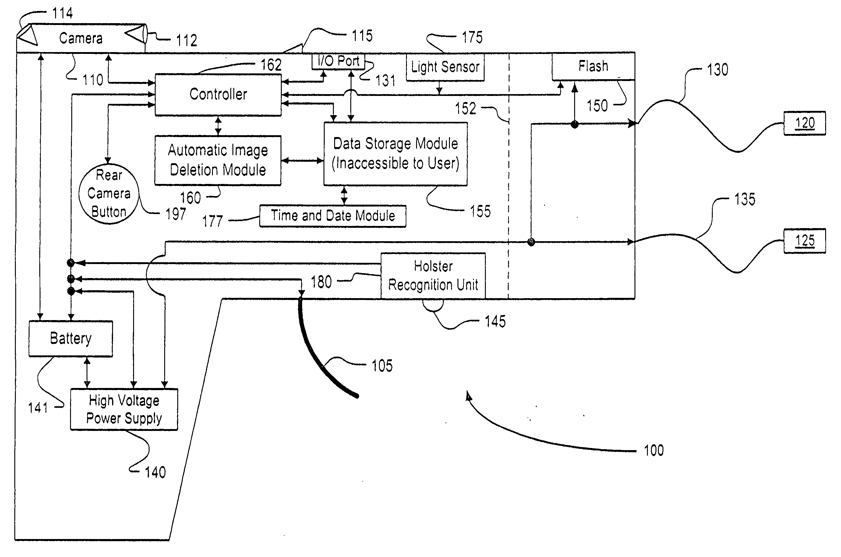
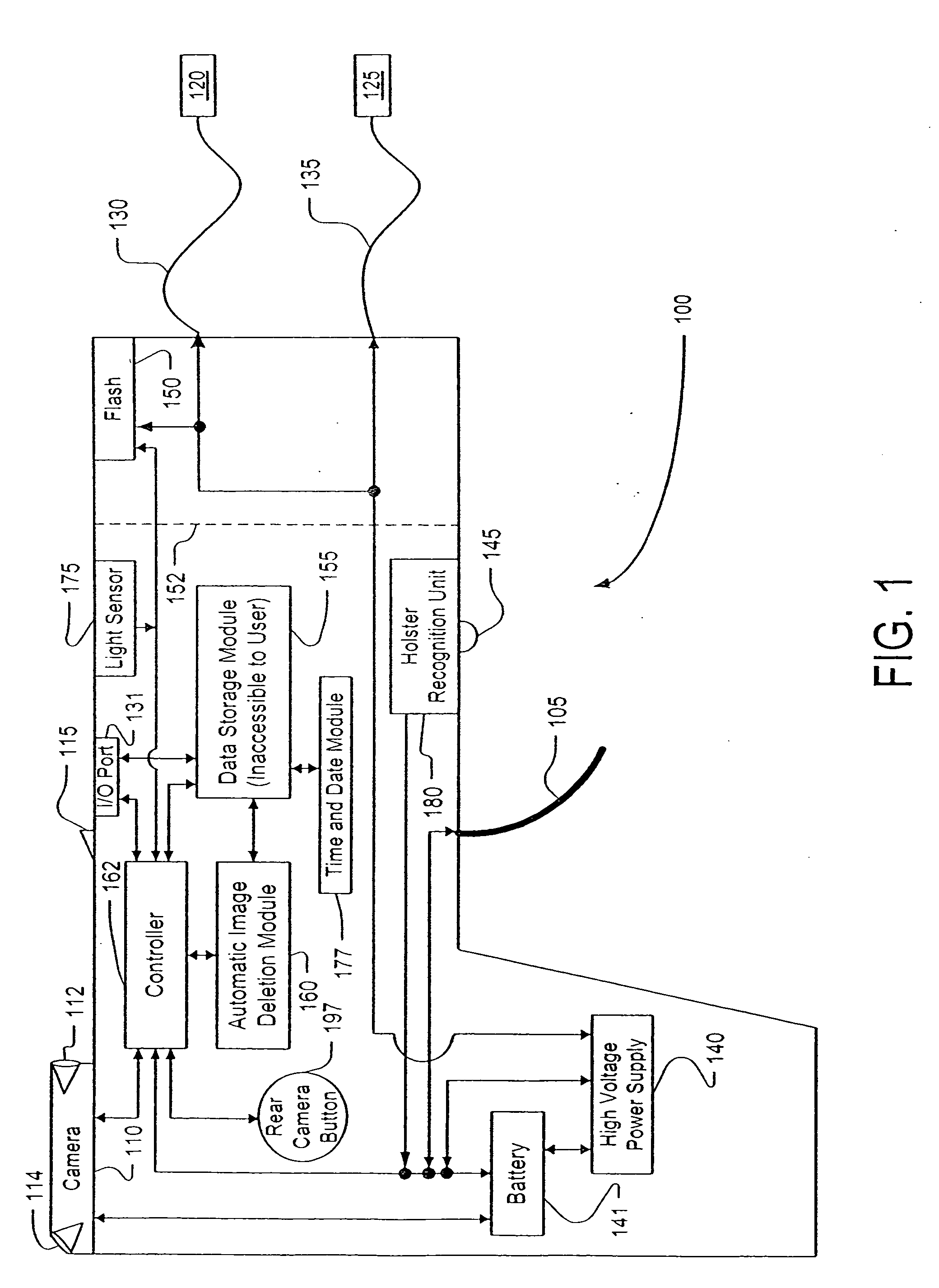
[0028]In order to more fully understand the present invention, an embodiment thereof is illustrated in accompanying FIG. 1. The relative positions of the various components shown in FIG. 1 are exemplary only, and considerable variation of those positions is acceptable. The gun 100 is a handheld stun gun that fires projectiles 120 and 125 (hereinafter “firing” the stun gun refers to beginning to deliver a shock either with or without shooting projectiles, unless otherwise indicated). These projectiles, such as darts, are connected to the gun by respective wires 130 and 135, which are linked to a high power voltage supply 140 that is powered by a battery 141. This same battery 141 can also power a camera 110. When the firing mechanism 105 is activated (by contact with a user's finger), the battery 141 supplies power to the camera 110 so that the camera will capture an image shortly after the projectiles 120 and 125 are fired. The camera is shown toward the rear of the gun in FIG. 100,...


PUM


Abstract

A stun gun is disclosed having a firing mechanism, and also having a camera for automatically capturing post-firing images after the firing mechanism is activated. The post-firing image is automatically and digitally marked, or partly marked, to indicate when the camera was used. A method of gun operation is also presented, along with a system that includes both the gun and a gun holder. Removal of the gun from the gun holder may activate the camera's visual or audio collection capabilities, and further actions such as removal of a gun safety may heighten activation of the camera. The camera's visual collection capabilities include viewing both the target and also the user of the gun.

Description

CROSS-REFERENCE TO RELATED APPLICATIONS[0001]The present invention claims priority to U.S. Provisional Application 60 / 590,701 filed Jul. 23, 2004.BACKGROUND OF THE INVENTION1. Field of the Invention[0002]The present invention relates to guns, and in particular to security mechanisms to ensure proper use of guns. This invention is especially applicable to stun guns, for example stun guns that shoot one or more projectiles.[0003]2. Description of Related Art[0004]In this disclosure, the term “stun gun” is used broadly, and includes not only weapons that merely stun a target, but also weapons that induce electro-muscular disruption, either by firing one or more projectile at a target, or by simply prodding the target.[0005]Typically, two projectiles are connected to a stun gun by respective wires. The user of the stun gun can send an electrical shock to a target via the wires, and may also have the capability to send successive shocks while the wires are still connected to the target. ...

Claims


Application Information

Patent Timeline
Patent Type & Authority Applications(United States)
IPC IPC(8): G03B29/00
CPCH05C1/06F41H13/0025
Inventor FRESSOLA, ALFRED A.HYMAN, ANDREW T.FRESSOLA, BRENDAN A.
Owner FRESSOLA ALFRED A
Learn More