Backlight device, display device and television receiver
a technology of display device and backlight panel, which is applied in the direction of lighting support device, television system, instruments, etc., can solve the problems of degrading color hues and color purity on display panels, and achieve the effect of improving color hues and color purity on display and preventing the reduction of display panel brightness
- Summary
- Abstract
- Description
- Claims
- Application Information
AI Technical Summary
Benefits of technology
Problems solved by technology
Method used
Image
Examples
first embodiment
[0075]With reference to FIGS. 1 to 14, a description will be given of a liquid crystal television receiver 1 provided with a backlight device 20 according to a first embodiment of the present invention. The liquid crystal television receiver 1 is an example of the “television receiver” of the present invention.
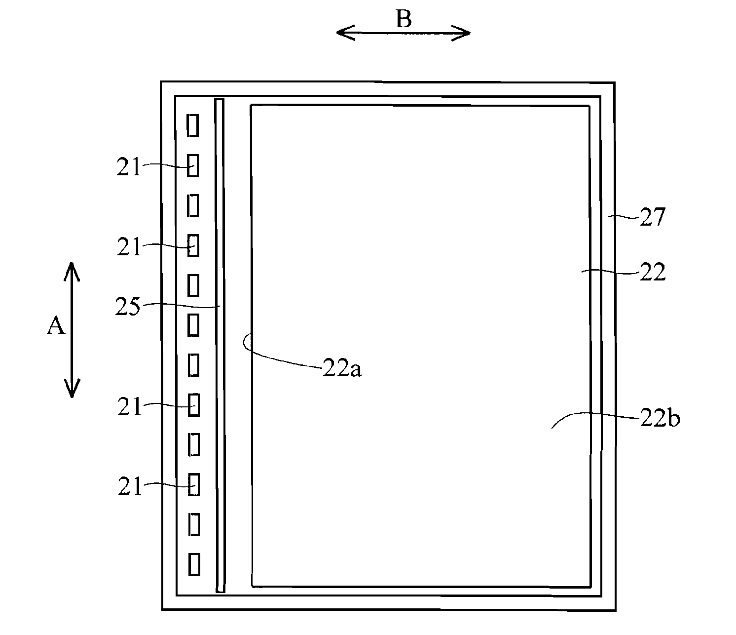
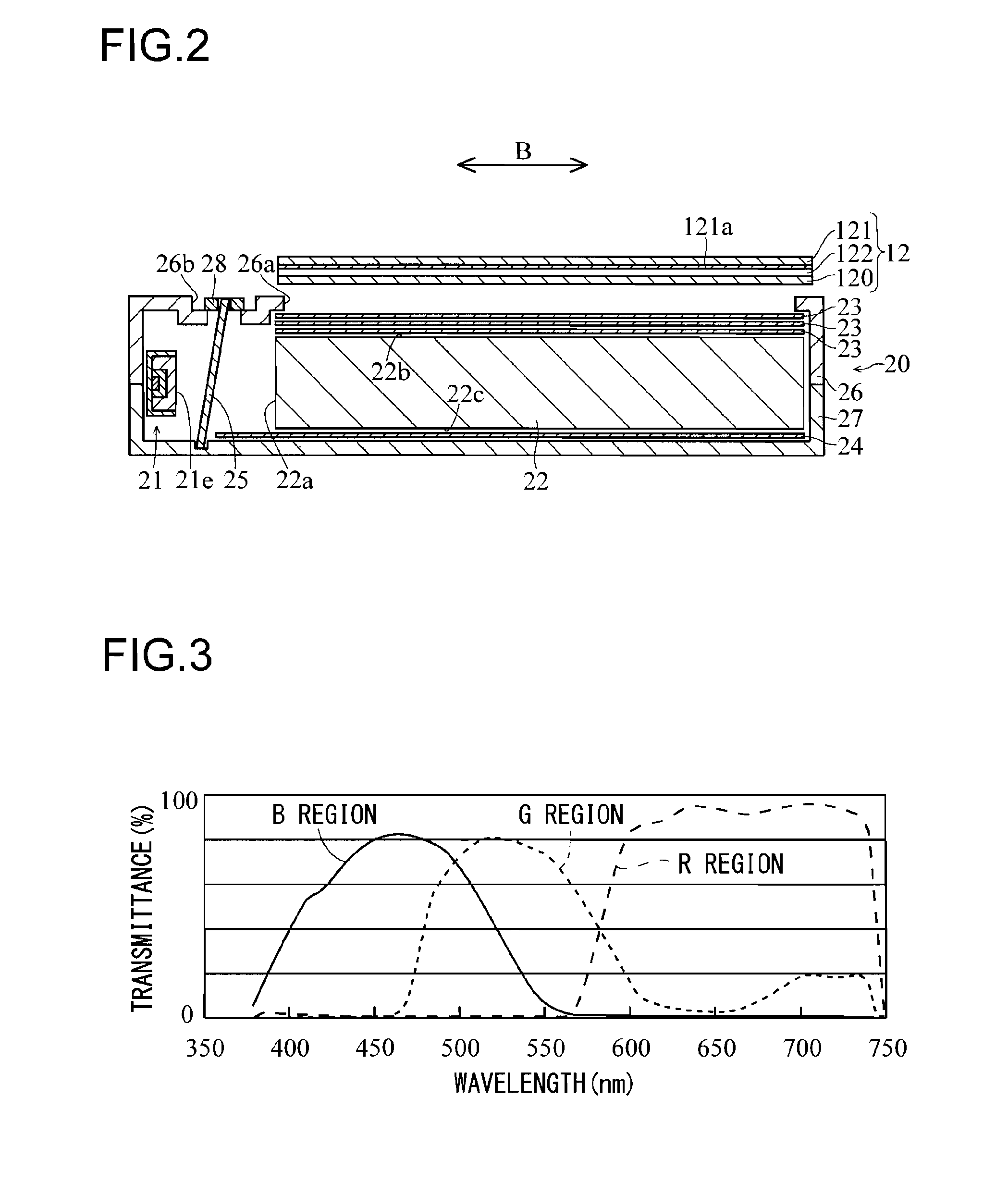
[0076]As shown in FIG. 1, the liquid crystal television receiver 1 provided with the backlight device 20 according to the first embodiment of the present invention is provided with: a liquid crystal display device 10 including the backlight device 20; a front cabinet 2 and a rear cabinet 3 housing the liquid crystal display device 10; a speaker 4 fitted to the front cabinet 2; a tuner 5; a power supply 6; and a support member 7. As the front cabinet 2, the rear cabinet 3, the speaker 4, the tuner 5, the power supply 6, and the support member 7, conventional ones that have commonly been used can be applied, and thus they will each be briefly described. The liquid crystal displa...
second embodiment
[0117]A description will be given of a second embodiment of the present invention with reference to FIGS. 15 and 16, and the description will deal with an example different from the first embodiment in that two dichroic filters 25 and 35 that respectively reflect light having different wavelengths (wavelength bands) are provided.
[0118]As shown in FIG. 15, a backlight device 30 is composed of a plurality of pseudo white LEDs 21, a light guide plate 22, a plurality of optical sheets 23, a reflection sheet 24, dichroic filters 25 and 35 arranged between the pseudo white LEDs 21 and the light guide plate 22, and a front chassis 36 and a rear chassis 37 in which these components are housed. The dichroic filter 25 is an example of the “filter member” and the “first filter member” of the present invention, and the dichroic filter 35 is an example of the “filter member” and the “second filter member” of the present invention. The front chassis 36 and the rear chassis 37 are an example of th...
third embodiment
[0134]A description will be given of a third embodiment of the present invention with reference to FIG. 17. The description will deal with an example in which, unlike the first embodiment, pseudo white LEDs 21 and a dichroic filter 25 are arranged on both sides of a light guide plate 22 in direction B.
[0135]As shown in FIG. 17, a backlight device 40 is composed of a plurality of pseudo white LEDs 21, a light guide plate 22 having a pair of light incident surfaces 22a, a plurality of optical sheets 23, a reflection sheet 24, two dichroic filters 25 arranged between the pseudo white LEDs 21 and the light guide plate 22, and a front chassis 46 and a rear chassis 47 in which these components are housed. The front chassis 46 and the rear chassis 47 are an example of the “housing member” of the present invention.
[0136]Here, in the third embodiment, the pseudo white LEDs 21 and the dichroic filters 25 are arranged on both side of the light guide plate 22 in direction B.
[0137]Also, in the t...
PUM
 Abstract
Description
Claims
Application Information
 - R&D
- Intellectual Property
- Life Sciences
- Materials
- Tech Scout
- Unparalleled Data Quality
- Higher Quality Content
- 60% Fewer Hallucinations
Browse by: Latest US Patents, China's latest patents, Technical Efficacy Thesaurus, Application Domain, Technology Topic, Popular Technical Reports.
© 2025 PatSnap. All rights reserved.Legal|Privacy policy|Modern Slavery Act Transparency Statement|Sitemap|About US| Contact US: help@patsnap.com


