
Inner-Rotor-Type Motor

a technology of inner-rotor-type motors and motors, which is applied in the direction of machines/engines, bearing units, liquid fuel engines, etc., can solve the problems of increasing assembly difficulties, and achieve the effect of improving the assembly convenience of inner-rotor-type motors

Active Publication Date: 2010-11-11
SUNONWEALTH ELECTRIC MACHINE IND
View PDF2 Cites 7 Cited by
  • Summary
  • Abstract
  • Description
  • Claims
  • Application Information

AI Technical Summary

Benefits of technology

[0008]It is therefore the primary objective of this invention to provide an inner-rotor-type motor that improves the assembly convenience of the inner-rotor-type motor.
[0010]Wherein a stopper is at least a part of the upper wall of the socket and arranged between the first recess and the second recess. The bearing can pass through an end of the socket and be positioned in the first recess, while a circuit board can pass through another end of the socket and be positioned in the second recess, for one to complete the assembly of the inner-rotor-type motor. Accordingly, the assembly is simplified and the assembly convenience is improved.
[0011]Wherein the socket has a plurality of slits arranged in the circumferential side wall of the socket and a plurality of coupling portions. Each one of the coupling portions is a laterally extending groove formed at the closed end of the slits. The slits and coupling portions communicate with the second recess, and thus wires of the stator are guided into the second recess through the slits of the socket. Accordingly, the assembly convenience is improved.

Problems solved by technology

With the trend toward miniaturization of the motor sizes, the conventional inner-rotor-type motor diminishes accordingly and the first recess 911 is barely enough to receive the bearing 84, so mounting the fastener 86 on the end of the shaft 831 in the first recess 911 is not easy in assembly, and thus increases the assembly difficulties.

Method used


Image

  • Inner-Rotor-Type Motor
  • Inner-Rotor-Type Motor
  • Inner-Rotor-Type Motor

Examples


Embodiment Construction

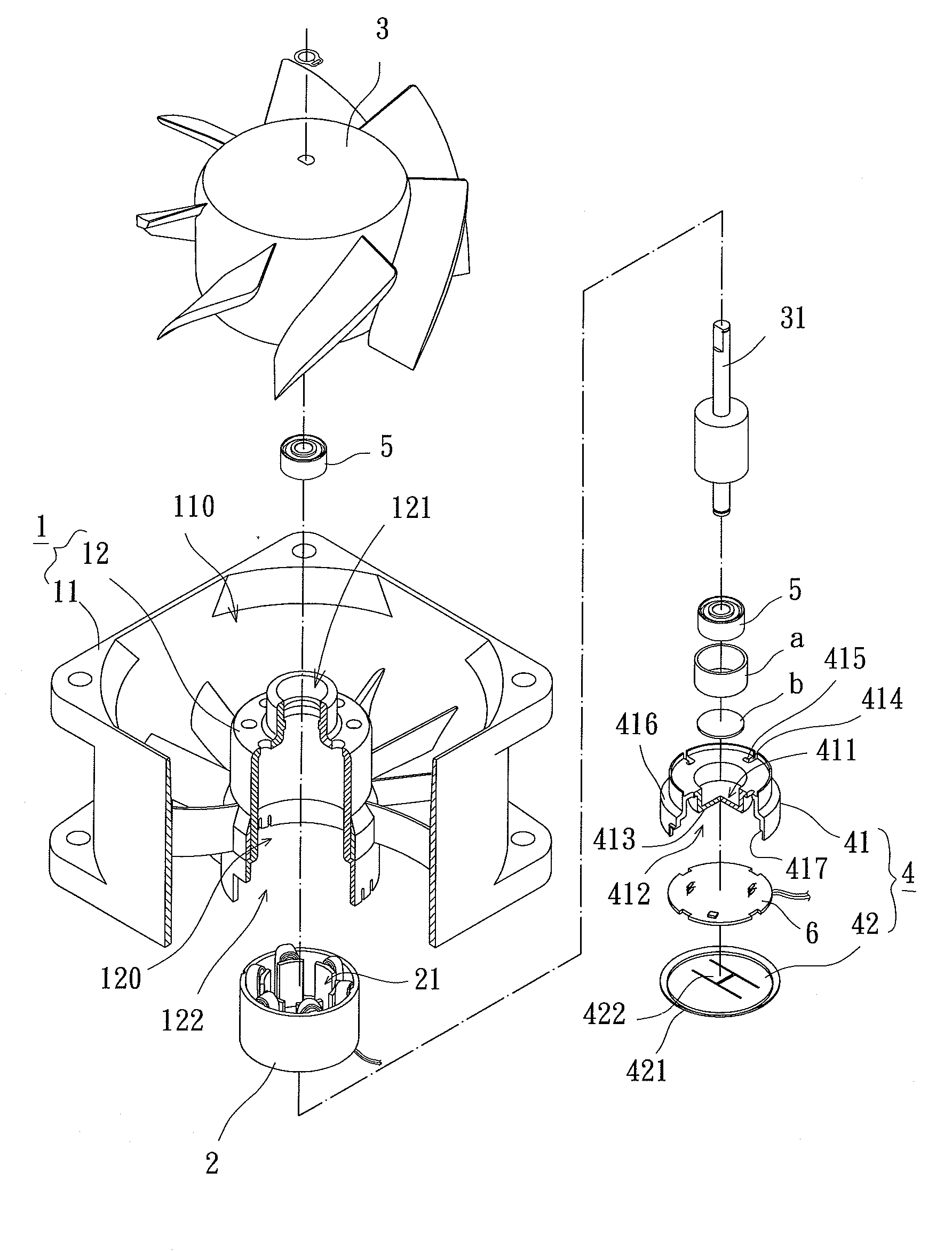
[0023]Referring to FIG. 3, the inner-rotor-type motor in accordance with the preferred teachings of the present invention includes a housing 1, a stator 2, a rotor 3 and a bearing seat 4. The stator 2 and the rotor 3 are received in the housing 1 and the bearing seat 4 is mounted on a bottom of the housing 1.

[0024]In detail, the housing 1 includes an outer shell 11 and an inner shell 12. The outer shell 11 has a compartment 110 to receive the inner shell 12. The inner shell 12 is a hollow shell with an assembly space 120, a shaft hole 121 and an assembly opening 122. The shaft hole 121 and the assembly opening 122 communicate with the top and the bottom of the assembly space 120 respectively. The stator 2 with a through-hole 21 is received in the assembly space 120. The through-hole 21 has two openings on two ends thereof communicating with the shaft hole 121 and the assembly opening 122 of the inner shell 12 in alignment. The rotor 3 has a shaft 31 arranged along an axle, and the s...


PUM


Abstract

An inner-rotor-type motor according to the preferred teachings of the present invention includes a housing, a stator, a rotor and a bearing seat. The stator is received in an assembly space of the housing. The rotor is rotatably positioned in the housing via a bearing and extends through a through-hole of the stator. The bearing seat includes a socket having a first recess and second recess and couples to the assembly opening of the assembly space. A stopper is at least a part of the upper wall of the socket and arranged between the first recess and the second recess. The bearing can pass through an end of the socket and be positioned in the first recess, while a circuit board can pass through another end of the socket and be positioned in the second recess. Accordingly, the assembly is simplified and the assembly convenience is improved.

Description

BACKGROUND OF THE INVENTION[0001]1. Field of the Invention[0002]The present invention relates to an inner-rotor-type motor and, more particularly, to an inner-rotor-type motor with a bearing seat.[0003]2. Description of the Related Art[0004]FIG. 1 shows a conventional inner-rotor-type motor 8 having a bottom for a bearing seat 9 to mount on. The inner-rotor-type motor 8 substantially includes a housing 81, a stator 82 and a rotor 83. The housing 81 has a compartment 810, an upper opening 811 and a lower opening 812. The upper opening 811 and the lower opening 812 communicate with the top and bottom of the compartment 810 respectively. The stator 82 with a through-hole 821 is mounted in the compartment 810. The through-hole 821 has two ends in the form of openings communicating with the upper opening 811 and the lower opening 812 in alignment. The rotor 83 has a shaft 831 arranged along an axle thereof. The rotor 83 is rotatably coupled to housing 81 through the bearing 84, with the ...

Claims


Application Information

Patent Timeline
Patent Type & Authority Applications(United States)
IPC IPC(8): H02K7/08
CPCF04D29/059F04D29/542F16C35/067F16C35/12H02K5/15F04D25/0606H02K7/083H02K7/14H02K11/0015H02K11/0073H02K5/1732H02K11/21H02K11/33
Inventor HORNG, ALEXLIU, CHENG-TESHAN, DUO-NIAN
Owner SUNONWEALTH ELECTRIC MACHINE IND
Learn More