
Electromechanical driver and remote surgical instrument attachment having computer assisted control capabilities

a technology of electronic motors and surgical instruments, applied in the field of medical devices, can solve the problems of increased unusable standard instruments, and special accommodations, and achieve the effect of improving the risk of contamination of surrounding tissues with bowel contents

Inactive Publication Date: 2010-11-04
COVIDIEN LP
View PDF101 Cites 533 Cited by
  • Summary
  • Abstract
  • Description
  • Claims
  • Application Information

AI Technical Summary

Benefits of technology

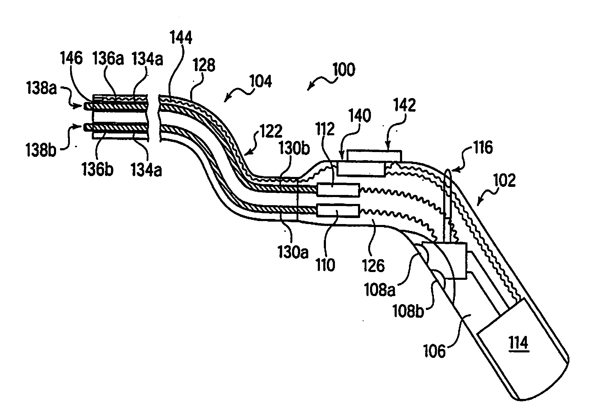
[0035]After recoupling, the anvil portion is retracted toward the stapling portion until it is mechanically determined that the two portions are within the range which is appropriate for staple firing. At this time, the physician user is unable to simply remotely fire the staples. This lock out feature is maintained by the processor unit until such time as the surgeon causes the processor until in the handle to query the tissue proximity sensor and the pulse oximeter sensor in the attachment to determine if the tissues to be stapled together form a completely contiguous ring so that the two tubular sections of bowel can be properly mechanically united. This measurement may be made optically, or by any other suitable means, by which the transmission of some signal which should be blocked by the intervening tissue is received by an opposing sensor. The results of this query are then relayed back to the processor in the handle which carries out the appropriate analysis. If the proximity query results in a negative analysis outcome, an indicator light, audible alarm, or other suitable means of alerting the surgeon to this condition is provided. The processor will also disarm the stapling mechanism (by removing power to the drive mechanisms, for example) to prevent an attempted override by the surgeon.

Problems solved by technology

If the cancerous tissue is too far up the colon, for example, then the standard instrumentation provided is unusable, thus requiring special accommodations.
These accommodations generally increase the risk of contamination of the surrounding tissues with bowel contents, increase the length of the surgery and the corresponding need for anesthesia, and eliminate the benefits of precise anastomosing and stapling which comes from utilizing a mechanized device.
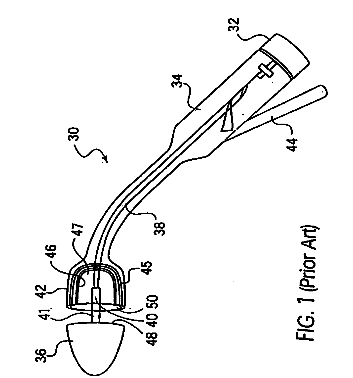
As with many such devices of the prior art, all of these devices are considered fully disposable, and are, in fact, thrown away after a single use.
They are complicated devices, having multiple moving parts, requiring substantial structural integrity and, therefore, expense in manufacturing.
The fact that they are used only once, and that no part can be used again, render the use of such devices expensive and wasteful of resources.
In addition to this failure, as can be readily observed from the preceding descriptions, the prior art devices suffer from numerous other limitations which would be desirable to overcome.
An observed problem with prior art devices used in the anastomosing, stapling and resecting surgical procedure described above, relates to the best indications which the surgeon may remotely receive as to the conditions within the patients colon.
Post surgical infection rates due to such failures are a leading cause of complications and are often severe and are a leading cause of morbidity.
An associated issue of which surgeons who carry out these procedures must be cognizant relates to the ongoing viability of the tissue which has been resealed.
A frequent post-surgical problem relates to the tissue necrosis which may occur if the staple ring is too tightly compressing the tissue, and preventing necessary blood flow thereto.
A simple light-based mechanically measured distance indicator means is insufficient to avoid both of these problem.
Prior art devices fail to provide the means by which information regarding the state of the tissue being manipulated may be measured and used by the surgeon, and the instrument itself, to ensure a more positive outcome.
It shall be understood that this problem, i.e., the failure of remotely controlled surgical instruments to provide for the gathering, displaying, and influencing of automatic actions, of information critical to the success of the surgical procedure simultaneously with the action of the device, is not limited to the specific instances discussed above.
Rather, this failure is prevalent throughout surgical instrumentation.

Method used


Image

  • Electromechanical driver and remote surgical instrument attachment having computer assisted control capabilities
  • Electromechanical driver and remote surgical instrument attachment having computer assisted control capabilities
  • Electromechanical driver and remote surgical instrument attachment having computer assisted control capabilities

Examples


Embodiment Construction

[0042]While the present invention will be described more fully hereinafter with reference to the accompanying drawings, in which particular embodiments are shown, and with respect to methods of surgical use, it is to be understood at the outset that persons skilled in the art may modify the invention herein described while achieving the functions and results of this invention. Accordingly, the descriptions which follow are to be understood as illustrative and exemplary of specific structures, aspects and features within the broad scope of the present invention and not as limiting of such broad scope. Like numbers refer to similar features of like elements throughout.

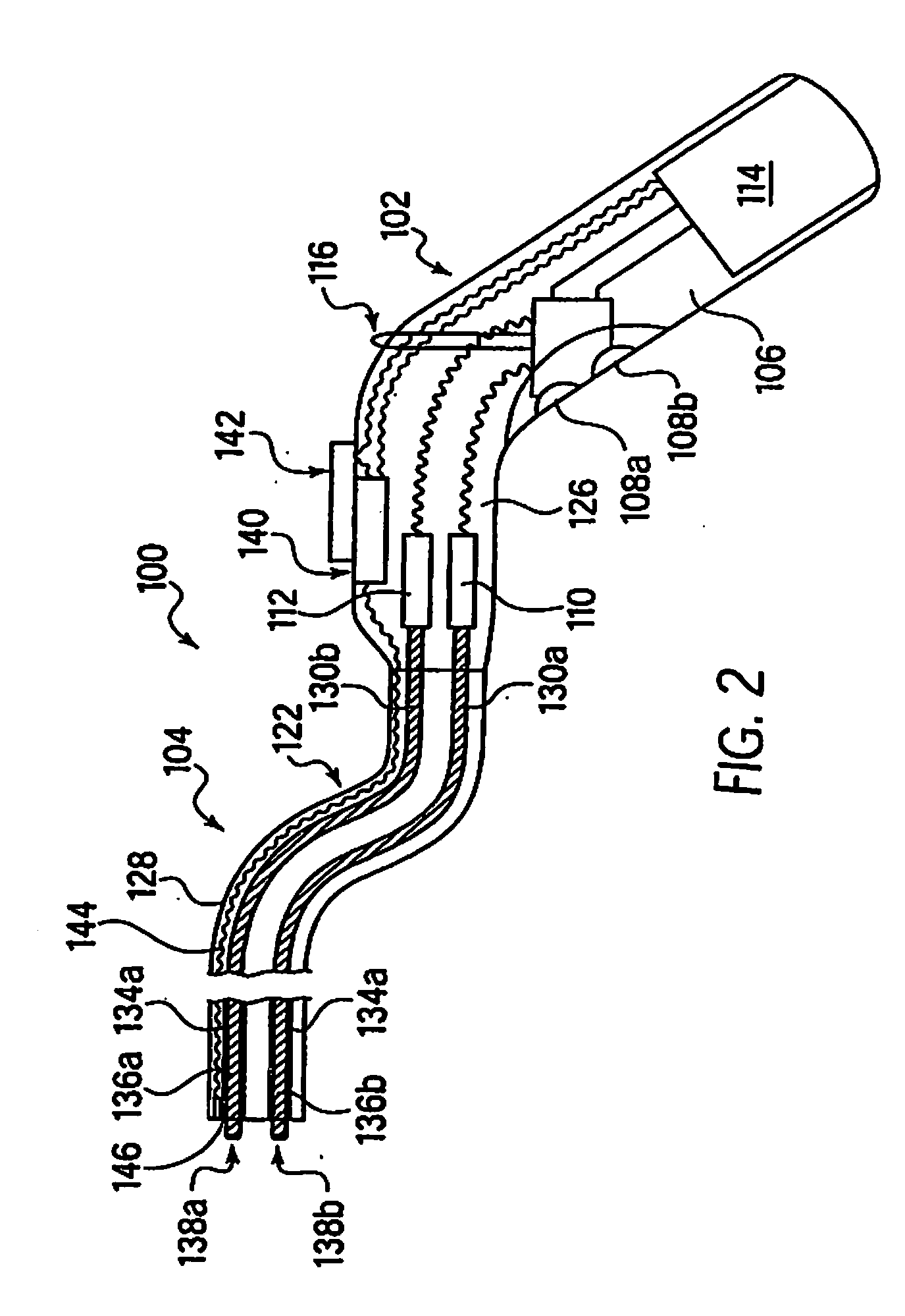
[0043]Referring now to FIG. 2, with respect to the electromechanical driver 100, the driver has a handle portion 102 and a flexible drive shaft portion 104. The handle 102 includes a portion which is shaped in a manner which is easily gripped by the surgeon operator, for example, in the embodiment provided herein the han...


PUM


Abstract

A medical tool comprising an electromechanical driver and a surgical instrument attachment for use in invasive surgery, including a handle coupled to a flexible sheath which is in turn coupled to a surgical attachment. The handle of the driver includes the electromechanical driver and at least one processor element which controls the actions of the electromechanical driver, and therefore the application elements of the surgical attachment, based on information relayed between the processor element and remotely activateable sensor assemblies in the surgical instrument attachment.

Description

RELATED APPLICATIONS[0001]This application is a continuation of and claims benefit of priority to Applicant's U.S. patent application Ser. No. 10 / 761,491, entitled “Electromechanical Driver and Remote Surgical Instrument Attachment Having Computer Assisted Control Capabilities”, filed Jan. 20, 2004, and issuing as U.S. Pat. No. 7,077,856, on Jul. 18, 2006, which is a division of U.S. patent application Ser. No. 09 / 510,927, filed Feb. 22, 2000, now issued as U.S. Pat. No. 6,716,233, the disclosures of which are hereby fully incorporated by reference.FIELD OF THE INVENTION[0002]The present invention relates generally to a medical tool comprising an electromechanical driver which transmits information to and receives information from, and thereby controls, a surgical instrument attachment, and more specifically to the mechanisms employed to provide such remote direction and information relaying between said electromechanical driver and said surgical instrument attachment.BACKGROUND[000...

Claims


Application Information

Patent Timeline
Patent Type & Authority Applications(United States)
IPC IPC(8): A61B17/068A61B17/00A61B17/072A61B17/11A61B17/115A61B17/28
CPCA61B5/1459A61B2017/2905A61B17/07207A61B17/1114A61B17/115A61B17/1155A61B2017/00022A61B2017/00039A61B2017/00292A61B2017/00398A61B2017/00464A61B2017/00473A61B2017/00734A61B2017/07214A61B2017/07278A61B5/6885A61B17/068A61B17/1152A61B2017/00367
Inventor WHITMAN, MICHAEL P.
Owner COVIDIEN LP
Learn More