
Method and devices for controlling a vapour flow in vacuum evaporation

a technology of vacuum evaporation and vapour flow, which is applied in vacuum evaporation coating, chemical vapor deposition coating, coating, etc., can solve the problems of serious damage to galvanisation installation caused by zinc contamination, and achieve the effect of simplifying the design of the vapour flow regulation device and preventing any condensation of zinc vapour

Active Publication Date: 2010-10-28
NEOVAC GMBH
View PDF4 Cites 5 Cited by
  • Summary
  • Abstract
  • Description
  • Claims
  • Application Information

AI Technical Summary

Benefits of technology

[0004]It will easily be understood that it is necessary to be able to adapt the electrical power delivered to the plasma and dissipated, via bombardment by ions issuing from the plasma, on the surface of the liquid zinc in the retention vessel according to the area of the steel substrate passing per unit of time through the confinement enclosure. In particular, cutting this electrical supply where no substrate is present, or is not passing, in the confinement enclosure, and conversely triggering and progressively increasing the electrical power dissipated on the surface of the liquid zinc when the substrate enters, or begins to pass in, the confinement enclosure. This is done so as not only to ensure a uniform thickness of zinc on the surface of the substrate but in particular to limit the losses of zinc through the entry and exit openings of the confinement enclosure when no substrate is passing through the confinement enclosure. This is because, apart from the economic loss, in terms of zinc and energy, the zinc contamination may seriously damage the galvanisation installation by plasma evaporation if it is not controlled.
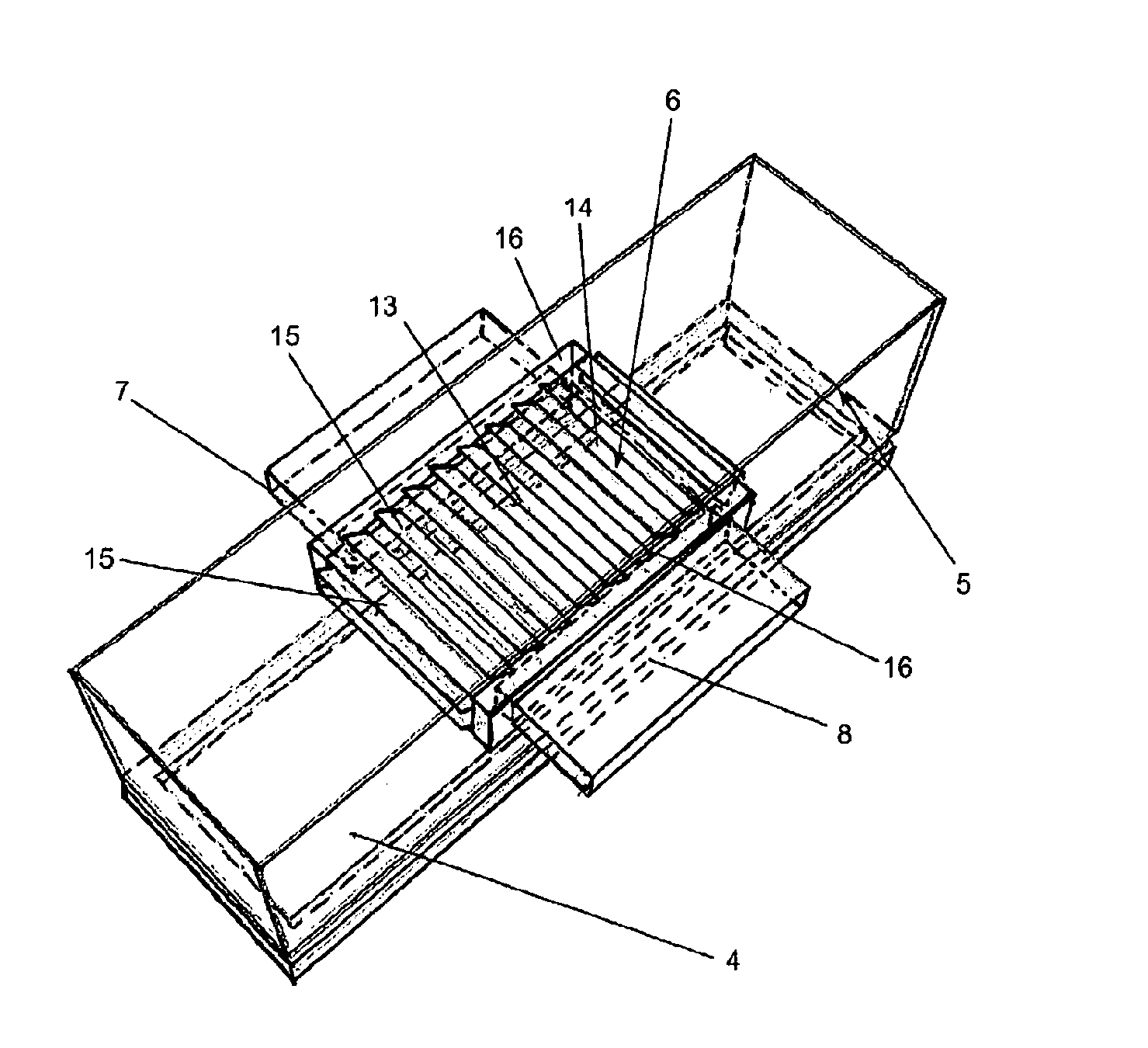
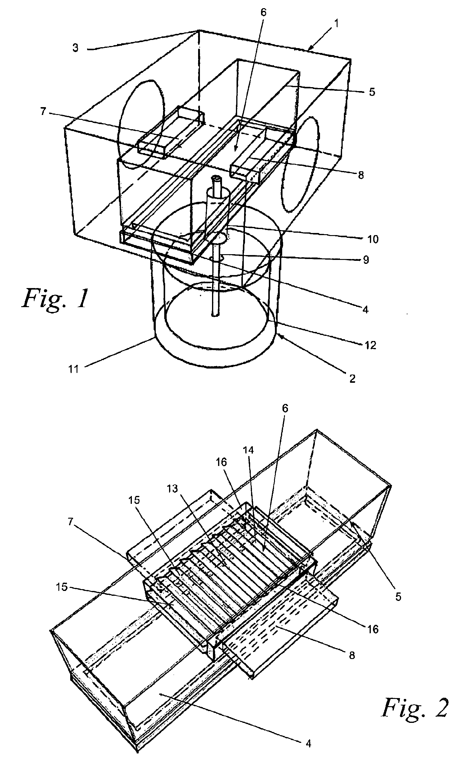
[0012]In a particularly advantageous configuration of the invention, a passage extends in the direction of travel of the substrates between an entry opening and an exit opening of the confinement enclosure, said treatment zone being situated in this passage and the regulation means being such as to make it possible to control the flow of said vapour between said vapour source and the inside of the passage.
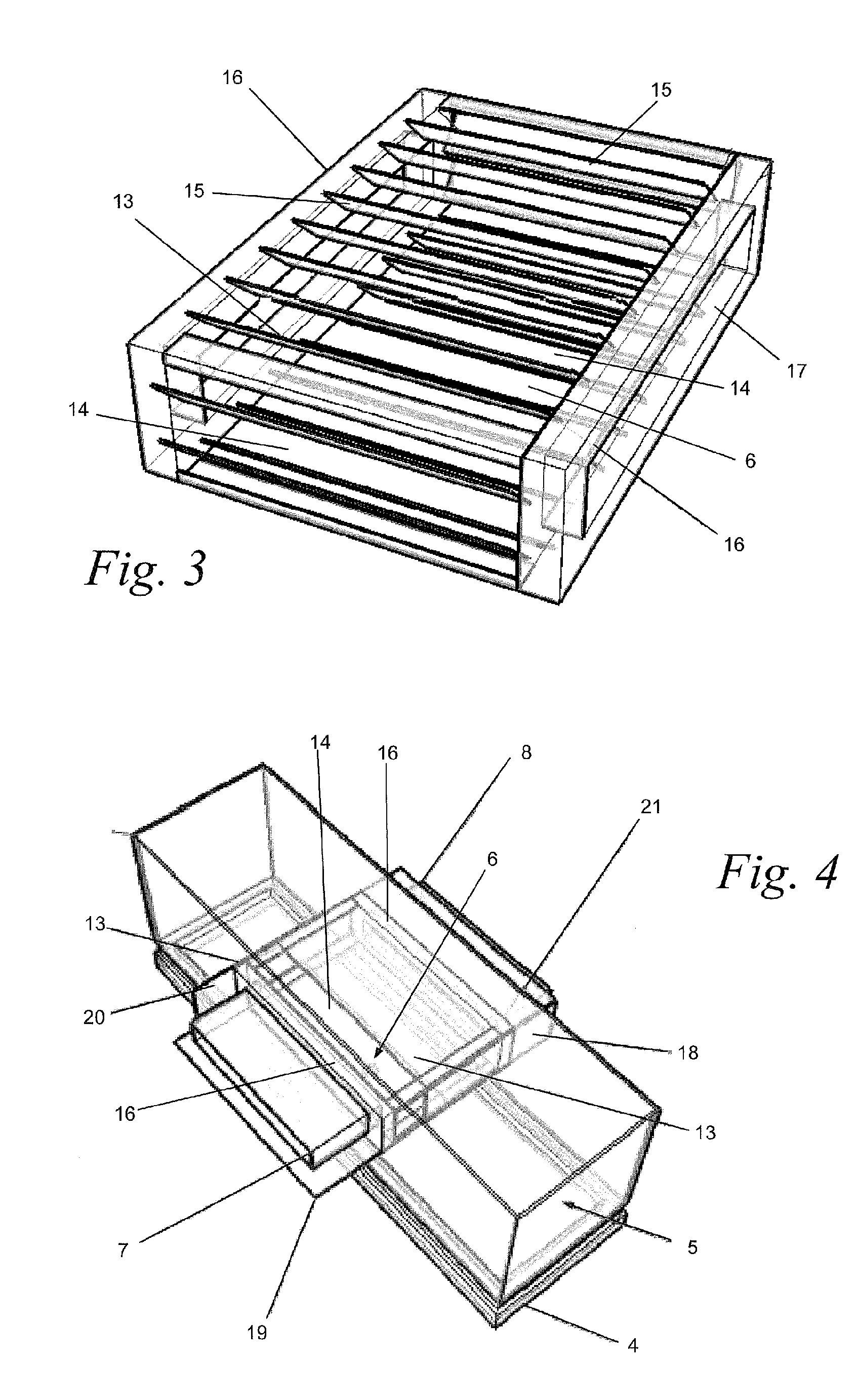
[0014]A device for heating, for example by Joule effect, the wall of the confinement enclosure is provided and sized so as to achieve a wall temperature sufficient to prevent any solid or liquid condensation of the metal vapour on said walls. This system for heating the confinement enclosure can also advantageously enable, by radiation, the maintenance at the same temperature, preventing any condensation of the zinc vapour, of the walls making up the passage for regulating the flow of vapour passing through the confinement enclosure. This makes it possible to simplify the design of the vapour flow regulation device, which can simply make use of a simple mechanical construction consisting of obturation elements, generally of any geometry, able to be moved between an open position, in which the flow of said vapour can pass through the treatment opening towards the treatment zone, and a closed position in which the treatment zone is isolated with respect to the vapour source generally with any geometry.

Problems solved by technology

This is because, apart from the economic loss, in terms of zinc and energy, the zinc contamination may seriously damage the galvanisation installation by plasma evaporation if it is not controlled.

Method used


Image

  • Method and devices for controlling a vapour flow in vacuum evaporation
  • Method and devices for controlling a vapour flow in vacuum evaporation
  • Method and devices for controlling a vapour flow in vacuum evaporation

Examples


Embodiment Construction

[0025]As shown in FIG. 1, the galvanisation device according to the prior art consists of top equipment 1 through which the substrate to be coated passes and bottom equipment 2 comprising a liquid zinc reserve.

[0026]The top equipment 1 comprises a vacuum chamber 3 in which there is arranged a vapour source formed by a retention vessel 4 surmounted by a confinement enclosure 5. The confinement enclosure has heated walls in order to prevent the deposition of vapour on these walls and is tubular in shape enabling steam to circulate freely and be distributed all around the product to be coated without any leakage of vapour in a direction transverse to the direction of movement of the substrate to be coated.

[0027]The liquid zinc that is present in the retention vessel 4 is evaporated by a plasma generated in the confinement enclosure 5 in order to create a flow of zinc vapour towards a treatment zone 6 that the substrate to be coated passes through. This treatment zone 6 extends between ...


PUM

PropertyMeasurementUnit
Pressureaaaaaaaaaa
Temperatureaaaaaaaaaa
Flow rateaaaaaaaaaa

Abstract

The invention relates to a method and a device for the coating of running substrates (25) moving along a run direction through a treatment zone (6), in which the vapour of a coating material is generated in a chamber (5), this vapour passing through a treatment aperture towards the treatment zone (6) where the coating material condenses on the surface of the substrates (25). The vapour flow through the treatment aperture is controlled by adjusting the extent to which the treatment aperture is shut off by at least one shutter (13), between an open position, in which said vapour flows through the treatment aperture towards the treatment zone (6), and a closed position, in which the vapour is prevented from flowing towards the treatment zone (6) through the treatment aperture.

Description

1. GENERAL DESCRIPTION OF THE INVENTION[0001]The invention relates to a method and device for the coating of running substrates, moving in a direction of travel, this device comprising a confinement enclosure in which a source of vapour of the coating material is present and having a treatment zone communicating with the source of vapour through at least one treatment opening. The source of vapour makes it possible to generate a flow of vapour for coating a substrate. The invention therefore concerns a device and method for controlling a flow of vapour towards a substrate to be coated in a vacuum evaporation coating method. The invention is particularly advantageous for the control and regulation of a flow of zinc vapour, obtained by evaporation of the metal, towards steel substrates in the form of strips, girders, plates, profiles, with all types of transverse sections, but also parts disposed on supports, for example hooks or metal baskets, transported in the coating zone.[0002]Al...

Claims


Application Information

Patent Timeline
IPC IPC(8): C23C14/14C23C14/56C23C14/24C23C14/22C23C14/32C23C14/54
CPCC23C14/16C23C14/246C23C14/562C23C14/542C23C14/32C23C14/14C23C14/24C23C14/54C23C14/56C23C14/243C23C14/325
Inventor VANDEN BRANDE, PIERRE
Owner NEOVAC GMBH
Learn More