
Method and system for registering and measuring leaks and flows

a leak and flow technology, applied in the field of methods of registering and measuring leaks and flows, can solve the problems of operators' significant cost savings, serious problems for operators, and leaks in principle, and achieve the effect of increasing detection precision

Inactive Publication Date: 2010-10-21
ARCHER SA
View PDF17 Cites 88 Cited by
  • Summary
  • Abstract
  • Description
  • Claims
  • Application Information

AI Technical Summary

Benefits of technology

[0025]An object of the present invention is to increase the precision of detection, and to localize virtually every leak in wells, pipelines and similar.
[0026]A further object of the invention is to provide methods of signal processing for detecting leaks in wells which are less computationally intensive and thereby, for a given computing capacity, enable more rapid detection of leaks in wells.

Problems solved by technology

Leaks in oil- and / or gas-producing wells potentially cause serious problems for operators, both with regard to safety and economics.
Such leaks may in principle occur anywhere where there is a barrier between two volumes when a pressure difference exists in operation between the two volumes.
By correcting such leaks, operators may potentially save considerable costs.
The system is employed principally in water pipes, but is susceptible to being optionally utilized in other fluid-conducting pipelines, for example where these pipelines are buried below ground level.
A technical problem encountered in respect of the aforementioned known methods is that they are at least one of:(a) too time consuming;(b) require large amounts of computational effort;(c) are not able to adequately distinguish when more than one type of leak is substantially spatially coincident with another type of leak, for example in a vicinity of a complex fracture of a casing;(d) insufficiently precise when spatially detecting leaks, and / or insufficiently sensitive to identify virtually every leak in a well.

Method used


Image

  • Method and system for registering and measuring leaks and flows
  • Method and system for registering and measuring leaks and flows
  • Method and system for registering and measuring leaks and flows

Examples


Embodiment Construction

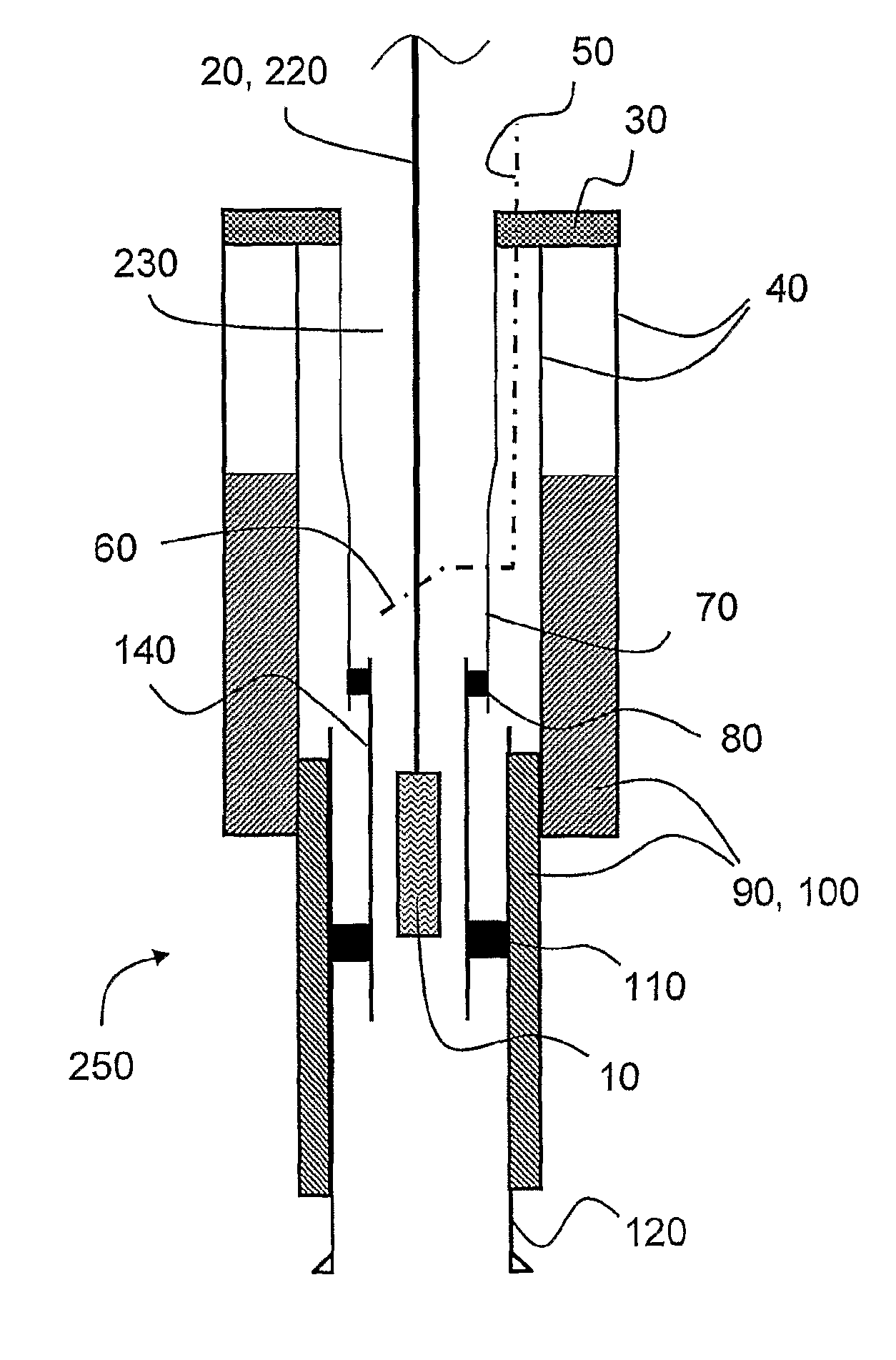
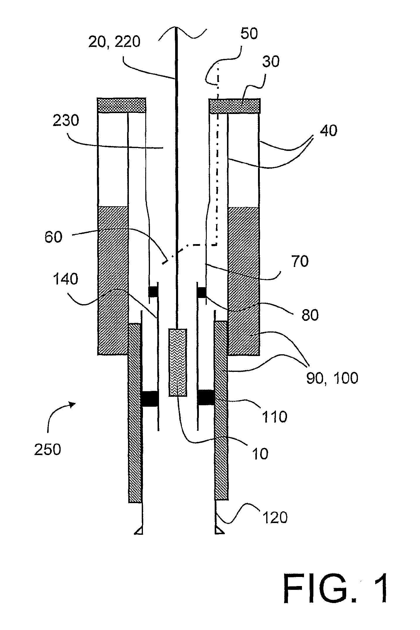
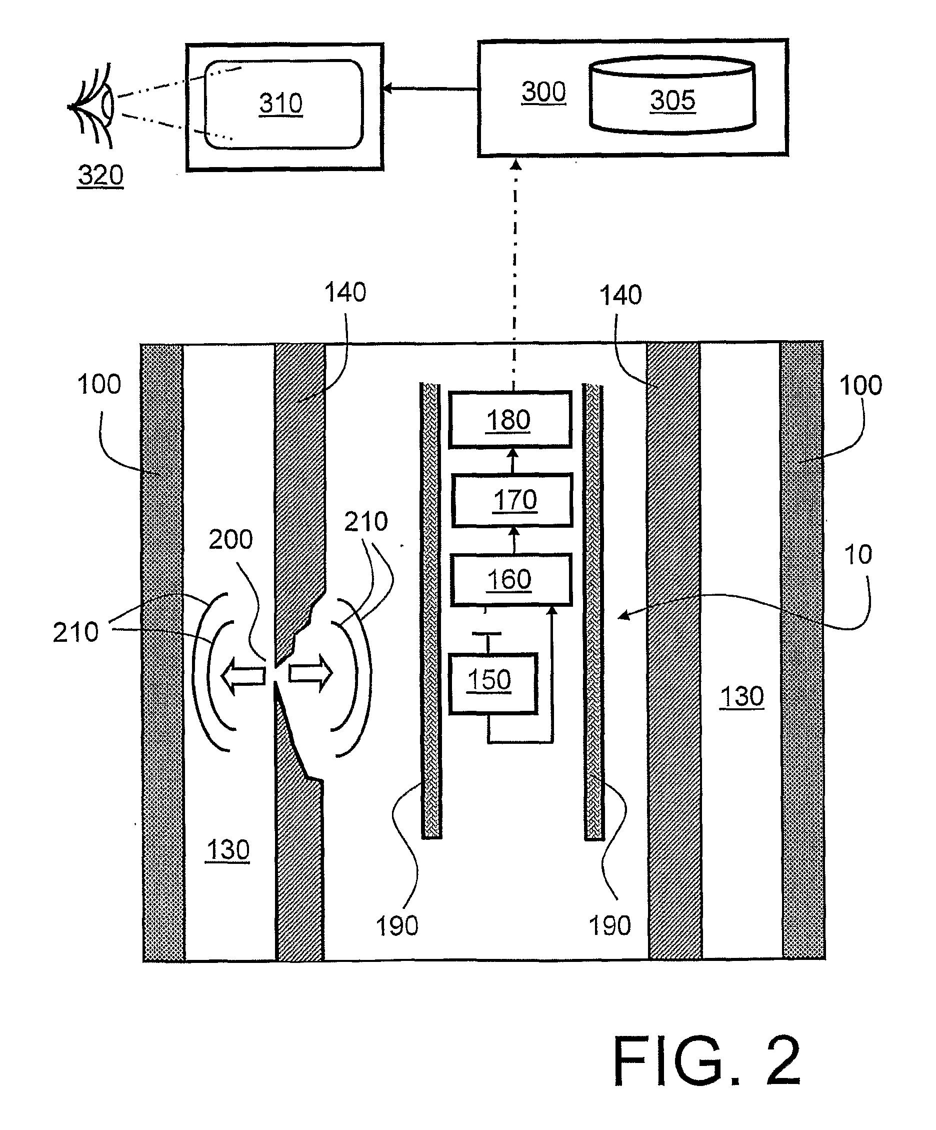
[0073]In summary, the present invention relates to a method of registering and measuring leaks and flows in a pipe by monitoring passive acoustic conditions in the pipe, for example in connection with oil and gas wells. The method utilizes one or more acoustic sensor elements to sense acoustic signals generated from several different acoustic sources arising within pipes and around pipes. The method differentiates the signals from each source through analysis. The invention also relates to a tool that comprises one or more acoustic sensor elements and a digital processing unit which operates within a pipe, and which may be moved continuously or stepwise in the longitudinal direction of the pipe.

[0074]Processes that partake as acoustic signal sources in a pipe may be:[0075](a) flow of fluids through the pipe;[0076](b) flow through leaks;[0077](c) annular flow in porous media in an external region outside the pipe;[0078](d) particles that hit the pipe wall or tool; and[0079](e) mechan...


PUM


Abstract

The present invention concerns a method of quantifying, detecting and localizing leaks or flows of liquid, gasses, or particles, in an oil or gas producing well (230). The method utilizes an acoustic transducer (150) arranged in the well (230). The method comprises steps of: (a) detecting signals (210) using the transducer (150), wherein the signals (210) are generated by acoustic noise from leaks (20) or flow of liquid, gasses, or particles in surroundings of the transducer (150); (b) amplifying the signals (210) to generate corresponding amplified signals for subsequent processing in a processing unit (170) disposed locally to the transducer (150); (c) filtering the amplified signals (210) over several frequency ranges using dynamic filtering for simultaneously detecting in these frequency ranges for better optimizing the signal-to-noise ratio by filtering away background noise in the amplified signals (210), and thereby generating corresponding processed data; and (d) sending the processed data from the processing unit (170) to a unit on the surface for storage and / or viewing of said data. The invention also comprises a corresponding system for implementing the method. The method and system are beneficially adapted for a continuous measurement up and / or down the oil or gas producing well. (230) in a non-stepwise manner.

Description

TECHNICAL FIELD OF THE INVENTION[0001]The present invention relates to methods of registering and measuring leaks and flows. Moreover, the invention concerns measuring systems operable to utilize aforesaid methods. Furthermore, the invention also relates to methods of using passive acoustic transducers in various spatial configurations and connections for detecting and localizing leaks and micro flows of liquids, gasses or particles in, or in connection with, oil- and / or gas-producing wells. Such measuring systems comprise logging tools which are lowered in operation down into wells by means of corresponding wires or coil pipes, the logging tools being utilized alone or as part of a logging string.BACKGROUND OF THE INVENTION[0002]Leaks in oil- and / or gas-producing wells potentially cause serious problems for operators, both with regard to safety and economics. Such leaks may in principle occur anywhere where there is a barrier between two volumes when a pressure difference exists in...

Claims


Application Information

Patent Timeline
IPC IPC(8): G01M3/24E21B47/10
CPCG01M3/246E21B47/101E21B47/107
Inventor LIE, TERJE LENNARTANDERSEN, GUNNARINSTANES, GEIR
Owner ARCHER SA
Learn More