
Graphics filled shape drawing

Inactive Publication Date: 2010-10-21
ARM LTD
View PDF2 Cites 32 Cited by
  • Summary
  • Abstract
  • Description
  • Claims
  • Application Information

AI Technical Summary

Benefits of technology

[0023]The present technique may be used both for immediate mode renderers and tile-based renders. When used with tile based renders, the plurality of graphics regions may comprise an array of graphics tiles of a common size. The tile-by-tile nature of the processing in generating the local shape data reduces memory traffic which is advantageous in increasing speed and reducing energy consumption.
[0025]When such fully occluded graphics regions are detected, all graphics objects having a greater depth within the graphics region concerned may be deleted from an object list of objects to be drawn for the graphics region. This reduces the processing overhead.
[0029]Each array of pixel values of a graphics region may be separately accessed from a memory. In this context, the present technique may be advantageous in permitting pixel values for pixels of the graphics region that are within the filled shape to be drawn and written during one access operation to the memory. This advantageously reduces memory traffic.
[0031]The present technique provides an advantage when used in systems that generate the local shape data by performing processing upon a bounding block comprising a plurality of graphics regions and surrounding the filled shape. Such bounding block approaches normally increase the amount of processing compared with only processing graphics regions that are intersected by the filled shape. The present technique helps reduce this additional processing burden.

Problems solved by technology

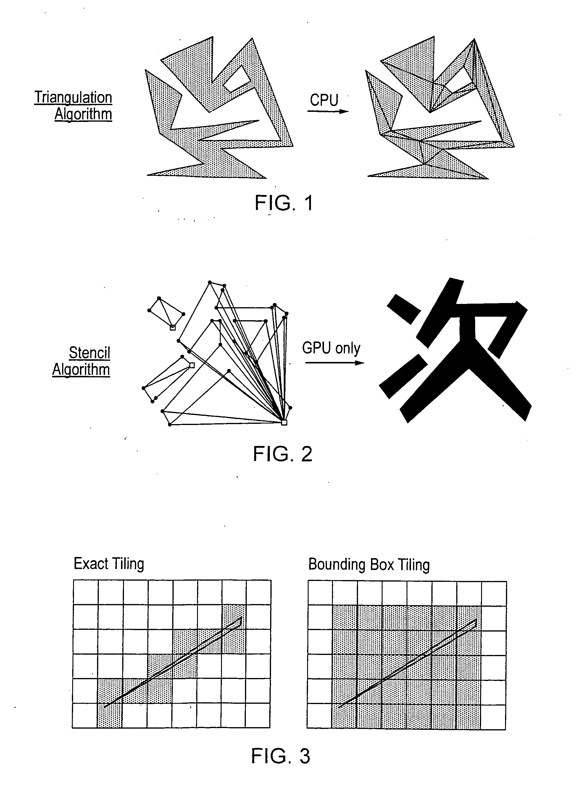
This local shape data does not produce the long, thin slivers associated with the stencil algorithm which result in the above discussed problems.
Furthermore, overdraw due to concave portions of the filled shape is limited to within the graphics region.

Method used


Image

  • Graphics filled shape drawing
  • Graphics filled shape drawing
  • Graphics filled shape drawing

Examples


Embodiment Construction

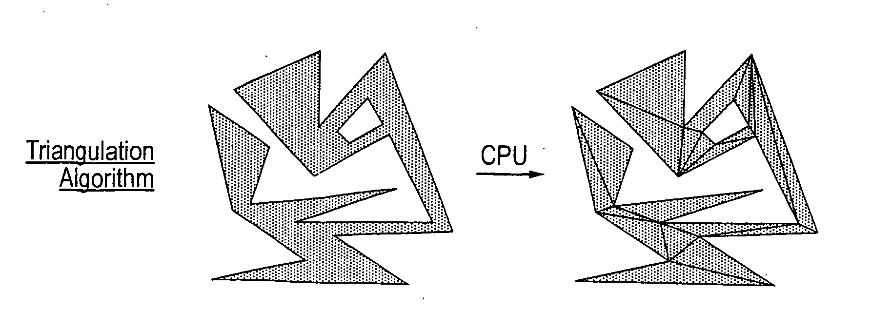
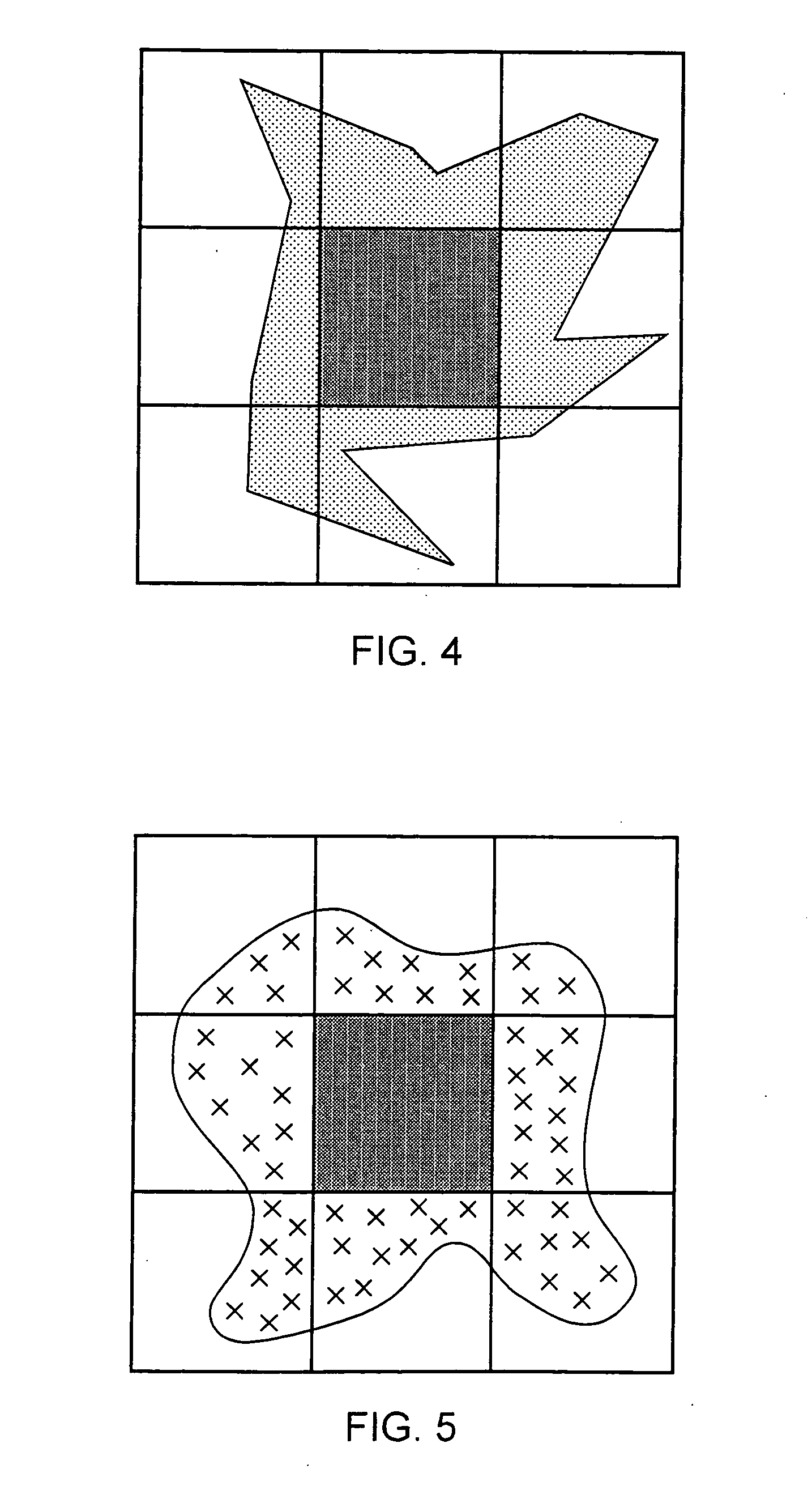
[0065]When triangulating polygons the problem is often considered globally—any edge may affect any pixel. However, this problem may be broken down into multiple local problems, e.g one problem per tile. If no edges cross a given tile, no pixels change state and so the visibility of the entire tile can be evaluated once for the entire tile.

[0066]FIG. 4 illustrates a filled shape with straight edges (polygon). FIG. 5 illustrates a filled shape with curved edges. It can be noted that since occlusion is known for the entire middle-tile, use of the stencil-technique can be avoided for this tile, thereby saving both fill-rate (complex polygons cause overdraw in the stencil-buffer), and reducing the triangle-count for that tile. All objects at a greater depth within an object list for the tile can be deleted as they will be overdrawn by the filled tile.

[0067]The local processing can be used to reduce overdraw; for a given tile only those edges that cross the tile need to be rendered. This ...


PUM


Abstract

A filled shape is defined by edge data forming one or more boundaries thereof. Local shape data is generated from the edge data for each graphics region overlapped by the filled shape. The local shape data separately represents for each graphic region at least any edge of the filled shape within the graphics region and an overlap value indicative of a difference between a number of times the boundaries of the filled shape surround the region in a clockwise direction and the number of times the boundaries surround the region in a counter-clockwise direction. For each graphics region having local shape data, the local shape data is used to generate pixel values for pixels within that graphics region that are within the filled shape to be drawn.

Description

BACKGROUND OF THE INVENTION[0001]1. Field of the Invention[0002]This invention relates to the field of graphics systems. More particularly, this invention relates to the drawing of filled shapes within graphics systems.[0003]2. Description of the Prior Art[0004]The use of vector graphics is increasingly popular within graphics systems in view of its speed and efficiency. Flash, OpenVG, SVG and GDI+ are examples of popular vector graphics applications and application programming interfaces used for drawing vector graphics. One of the significant performance-critical operations in these applications is the generation of pixel values for arbitrary filled shapes (such as polygons, shapes with curved edges or shapes with a mixture of curved and straight edges).[0005]One known technique for filled shape rasterization is to use a general purpose central processing unit. This approach favoured algorithms ill-suited to use within modern highly parallel graphics processing units. One way to a...

Claims


Application Information

Patent Timeline
IPC IPC(8): G06T11/20
CPCG06T11/40
Inventor LILAND, EIVINDFAYE-LUND, ERIKAMODT, ESPEN
Owner ARM LTD
Learn More